

Suspension device and accumulator
a suspension device and accumulator technology, applied in the direction of shock absorbers, mechanical devices, transportation and packaging, etc., can solve the problems of deterioration of the seal between and between, impaired durability, etc., to improve the roll stiffness of the vehicle, increase the pressure inside the accumulator, and improve the sealing pressure of a gas charged into the gas chamber
- Summary
- Abstract
- Description
- Claims
- Application Information
AI Technical Summary
Benefits of technology
Problems solved by technology
Method used
Image

Examples
Embodiment Construction
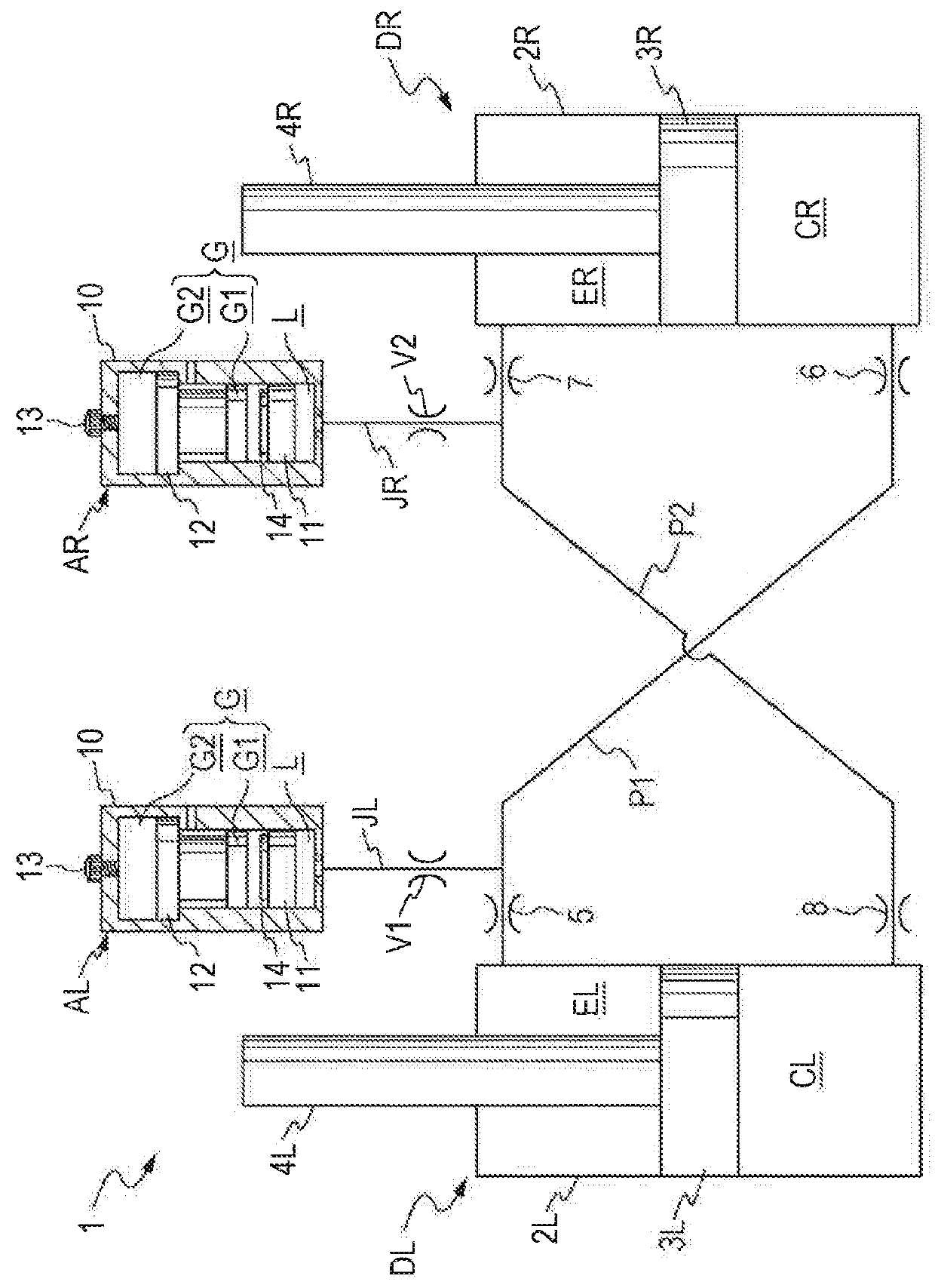
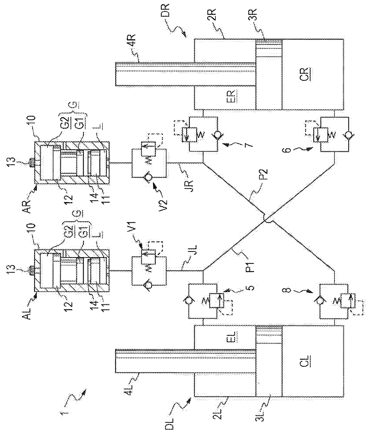
[0014]Hereinafter, embodiments of the invention will be described with reference to the drawings. A suspension device 1 of an embodiment of the invention includes a pair of liquid pressure dampers DL and DR, a first passage P1 which connects an extension side chamber EL of one liquid pressure damper DL and a compression side chamber CR of the other liquid pressure damper DR, a second passage P2 which connects a compression side chamber CL of one liquid pressure damper DL and an extension side chamber ER of the other liquid pressure damper DR, an accumulator AL which is connected to the first passage P1, and an accumulator AR which is connected to the second, passage P2 and is used so that the liquid pressure damper DL is interposed between a vehicle body and a left front wheel axle and the liquid pressure damper DR is interposed between the vehicle body and a right front wheel axle of, for example, a four-wheeled vehicle.
[0015]First, the liquid pressure dampers DL and DR include, as...
PUM
 Abstract
Description
Claims
Application Information