Machine learning device, CNC device and machine learning method for detecting indication of occurrence of chatter in tool for machine tool

a machine learning and cnc technology, applied in the field of machine learning devices, can solve problems such as poor machining of workpieces, large contact area, and more chatter

Active Publication Date: 2018-06-14
FANUC LTD
View PDF6 Cites 17 Cited by
  • Summary
  • Abstract
  • Description
  • Claims
  • Application Information

AI Technical Summary

Benefits of technology

[0014]The machine tool may include a vibration sensor which detects the vibration of the machine tool itself and provided in a holder or bit of the tool; and at least one of an audible sound sensor which detects the audible sound, and an acoustic emission sensor which detects the acoustic emission. The machine tool may include a vibration sensor which detects the vibration of the building in which the machine tool is installed. The machine tool may include a current sensor which detects a motor control current value of the machine tool. The current sensor may be provided in a motor amplifier for driving a motor of the machine tool.
[0015]According to a second aspect of the present invention, there is provided a CNC device including a learning circuit which constitutes the machine learning device according to the above described first aspect, and wherein the CNC device may control the machine tool. The CNC device may further include a determination c

Problems solved by technology

More specifically, for example, in a machining cycle such as thread cutting, the deeper a thread is cut, the larger the size of the contact area of the tool tip, and the more chatter tends to occur owing to the progression of wear.
An occurrence of chatter (occurrence of chatter in a tool for a machine tool) causes poor machining of workpieces.
Especially when a machine tool is brought into an automatic operation during evening hours, if one workpiece has chatter marks, every workpiece machined thereafter will also have chatter marks, thus producing a large number of poor workpieces.
Thus, for example, in the technique described in the patent document 1, the vibration acceleration (and the continuous time and variation

Method used


Image

  • Machine learning device, CNC device and machine learning method for detecting indication of occurrence of chatter in tool for machine tool
  • Machine learning device, CNC device and machine learning method for detecting indication of occurrence of chatter in tool for machine tool
  • Machine learning device, CNC device and machine learning method for detecting indication of occurrence of chatter in tool for machine tool

Examples


Embodiment Construction

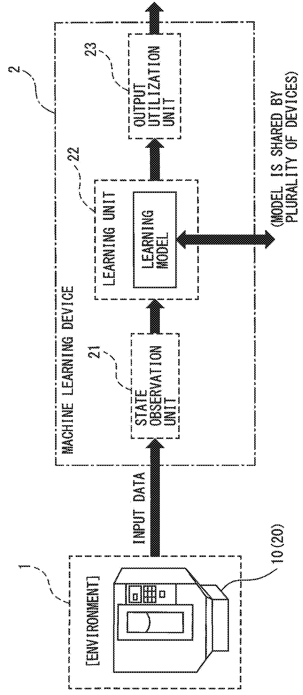
[0022]Hereinafter, embodiments of a machine learning device, a CNC device and a machine learning method according to the present invention will be described below in detail with reference to the accompanying drawings. FIG. 1 is a schematic block diagram of an embodiment of the machine learning device according to the present invention. As shown in FIG. 1, the machine learning device 2 according to the embodiment includes a state observation unit 21, a learning unit 22, and an output utilization unit 23.

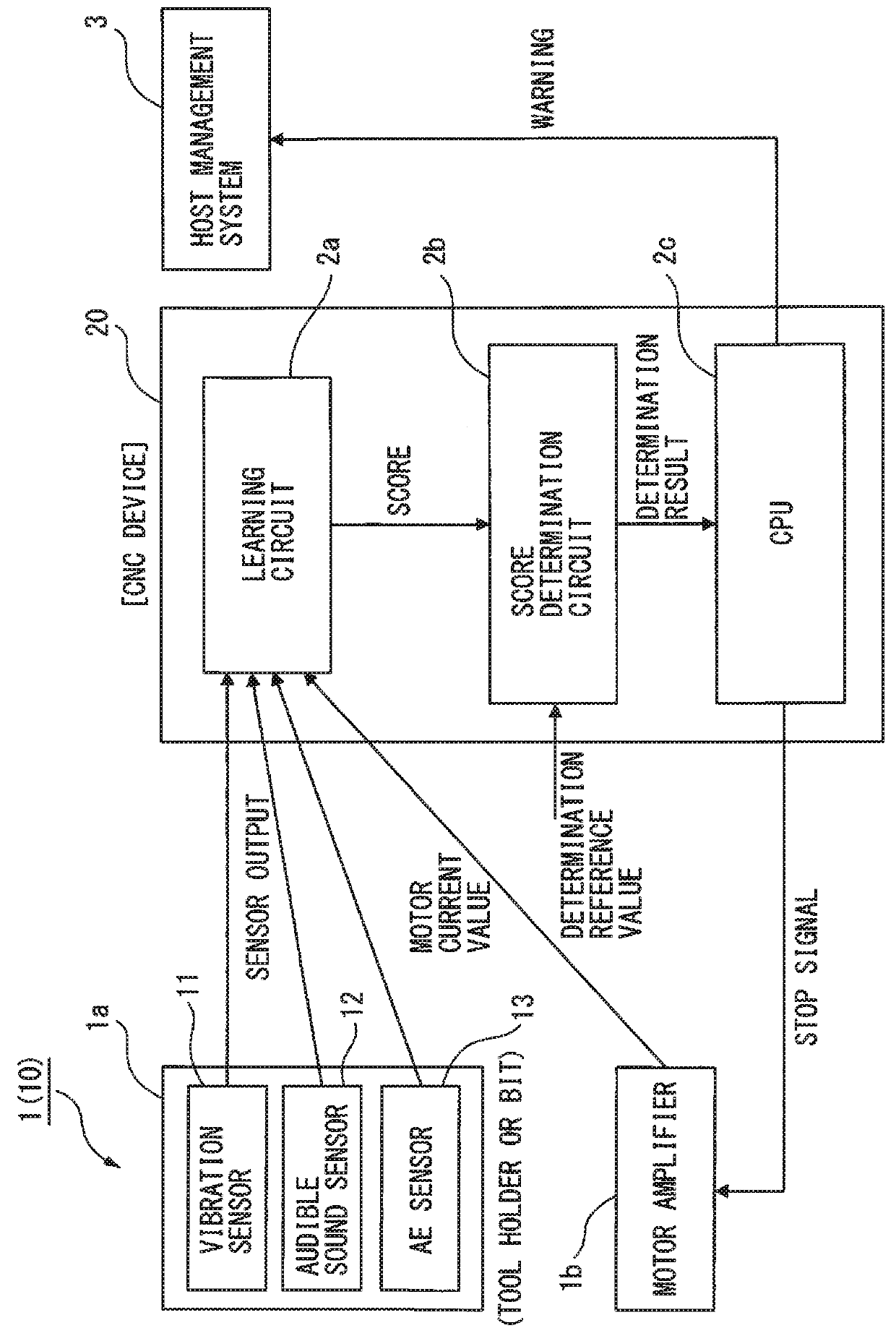
[0023]The state observation unit 21 receives, for example, the vibration of a tool of the machine tool 10 controlled by a CNC device 20, the vibration of the machine tool 10 itself, the vibration of a building in which the machine tool 10 is installed, an audible sound, an acoustic emission (AE waves and elastic waves) and a motor control current value of the machine tool 10, as input data supplied from the environment 1. The input data from the environment 1 to the state observation ...


PUM


Abstract

A machine learning device for detecting an indication of an occurrence of chatter in a tool for a machine tool, includes a state observation unit which observes at least one state variable of a vibration of the machine tool itself, a vibration of a building in which the machine tool is installed, an audible sound, an acoustic emission and a motor control current value of the machine tool, in addition to a vibration of the tool; and a learning unit which generates a learning model based on the state variable observed by the state observation unit.

Description

BACKGROUND OF THE INVENTION1. Field of the Invention[0001]The present invention relates to a machine learning device, a CNC device and a machine learning method for detecting an indication of an occurrence of chatter in a tool for a machine tool.2. Description of the Related Art[0002]Conventionally, in, for example, machine tools controlled by CNC (computer numerical control) devices, chatter sometimes occurs in a specific machining pass owing to the progression of wear of tools, even under the same machining conditions. More specifically, for example, in a machining cycle such as thread cutting, the deeper a thread is cut, the larger the size of the contact area of the tool tip, and the more chatter tends to occur owing to the progression of wear.[0003]An occurrence of chatter (occurrence of chatter in a tool for a machine tool) causes poor machining of workpieces. Especially when a machine tool is brought into an automatic operation during evening hours, if one workpiece has chatt...

Claims


Application Information

Patent Timeline
IPC IPC(8): G05B13/04G05B13/02
CPCG05B13/042G05B13/027G05B19/4142G05B2219/34013G05B19/406G06N3/088G05B2219/33296G05B2219/37433G05B2219/37434G06N3/045
Inventor MATSUSHIMA, TAKAHIKOMIYAZAKI, YOSHITO
Owner FANUC LTD
Why Eureka
Try Eureka