
Intelligent locomotive brake control system

a technology of intelligent brake control and locomotive, applied in the direction of braking system, braking components, transportation and packaging, etc., can solve the problems of complicated brake selection process, and inability to quickly on and off cycle the automatic brak

Active Publication Date: 2018-06-21
NEW YORK AIR BRAKE CORP
View PDF0 Cites 4 Cited by
  • Summary
  • Abstract
  • Description
  • Claims
  • Application Information

AI Technical Summary

Benefits of technology

The present invention is an intelligent braking system that can adjust braking operations to meet specific criteria set by the driver or a controller. The system can command different types of braking applications based on the driver's input or pre-configured parameters, while still achieving the overall braking result. The controller can prioritize certain criteria, such as reducing wear on brakes, minimizing in-train forces, and reducing subsequent power braking, to achieve the best braking effect. The system takes into account the train's current and future operation to select the most appropriate braking application.

Problems solved by technology

This length presents a number of issues as the train may be traveling over complex territory including curves and hills that require portions of the train to be braking while others are not.
This brake selection process is complicated by a number of factors.
The existence of slack between each rail car can further complicate the brake application.
In addition, release and recharge of the train (automatic) brake can take many minutes depending on the amount of brake applied, so rapid on and off cycling of the automatic brakes is not possible without depleting the train brake air supply.
If there is too much train brake set on a down grade and the train is slowing undesirably, rather than releasing the brakes, the train driver may increase the tractive power of the locomotive to pull the train down the grade against the train brakes.
This practice is known as “power braking” and is a clear waste of fuel and the brakes.
As result, high in-train forces can result as the rear of the train compresses the slack between each car and runs into the front of the train.
It is clear that in any situation, including an emergency, the train driver cannot possibly know and take into consideration the instantaneous train dynamics, the rate of brake propagation, the track geometry, and other factors for determining the optimum settings, such as bail-off and re-application of the locomotive brakes during an emergency stop.

Method used


Image

  • Intelligent locomotive brake control system
  • Intelligent locomotive brake control system
  • Intelligent locomotive brake control system

Examples


Embodiment Construction

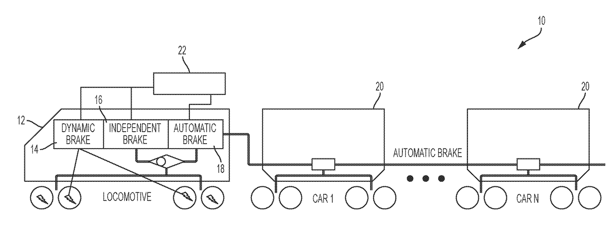
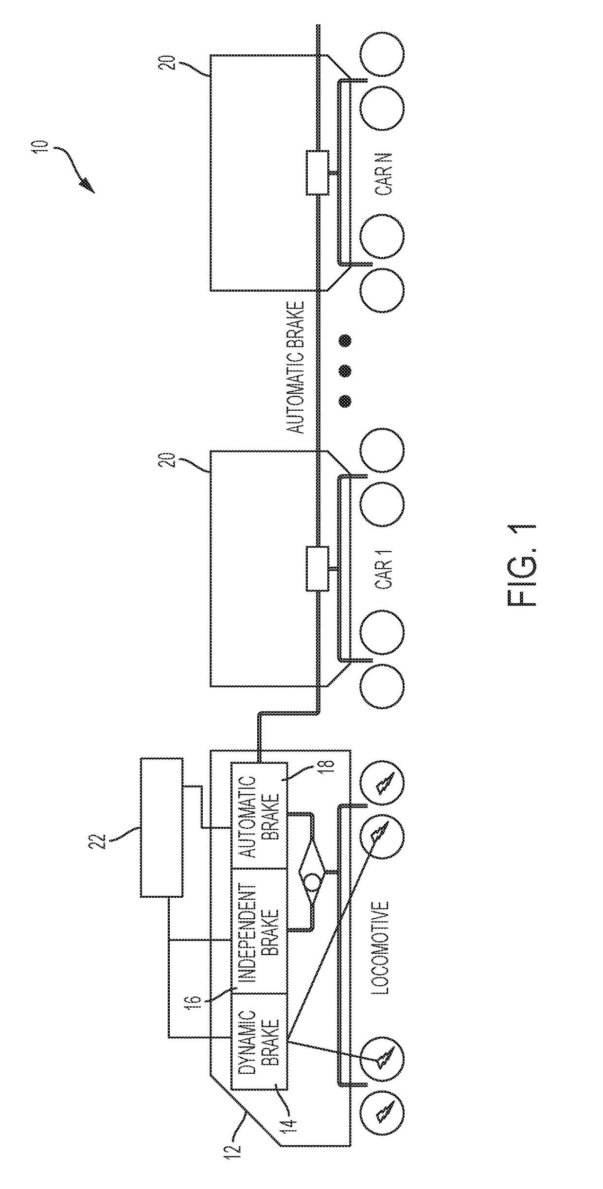
[0021]Referring to the figures, wherein like numerals refer to like parts throughout, there is seen in FIG. 1 an intelligent brake control system 10 for a locomotive 12 that interfaces with the existing dynamic brake 14 and independent brake 16 of the locomotive as well as the automatic brake 18 that applies the brakes of one or more rail cars 20 being pulled by the locomotive 12. System 10 may be configured as a standalone system, integrated into computer controller brake of a locomotive, or located in the energy management system (or a combination thereof).

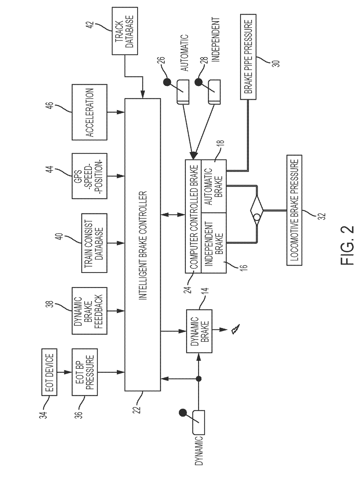
[0022]Referring to FIG. 2, system 10 comprises a main controller 22 that is in communication with or part of the computer controlled brake 24 of a locomotive. The computer controlled brake 24 is the locomotive equipment used to respond to train driver inputs by executing or commanding the brake settings as selected by the train driver, such as the CCB II® computer controlled brake available from New York Air Brake, LLC of Watert...


PUM


Abstract

An intelligent locomotive brake control system which selects and optimizes use of dynamic, independent, and automatic brakes on the locomotive to assure intended brake power, to minimize in-train forces, minimize brake component wear, and to automate standard train brake protocol. The system may be programmed to alter an automatic brake application commanded by a train driver to omit or reduce the amount of the automatic brake application in favor of a dynamic brake application, and independent brake application, or combination thereof.

Description

BACKGROUND OF THE INVENTION1. Field of the Invention[0001]The present invention relates to locomotive braking systems and, more particularly, to a locomotive brake system that can selectively apply the independent and dynamic brakes in response to an automatic brake application to account for current train conditions and track geometry.2. Description of the Related Art[0002]A locomotive typically has three separate, individually controlled brake systems. First, a locomotive has the independent brake that is a locomotive-only pneumatic brake controlled by the independent brake handle in the cab of the locomotive. Next, a locomotive has an automatic brake that applies the brakes on the train and on the locomotive by the automatic brake handle. Finally, the dynamic brake that provides braking power from the locomotive traction motors and is controlled by the dynamic brake handle in the cab of the locomotive.[0003]A train consisting of one or more locomotives and as many as 200 freight ...

Claims


Application Information

Patent Timeline
Patent Type & Authority Applications(United States)
IPC IPC(8): B61L15/00
CPCB61L15/009B61L15/0072B60T13/665B60T15/14B60T17/228B60T13/66
Inventor WRIGHT, ERIC C.REYNOLDS, JOHN M.
Owner NEW YORK AIR BRAKE CORP
Learn More