Feeding Device And Image Recording Apparatus Equipped With The Feeding Device

a technology of feeding device and image recording apparatus, which is applied in the direction of thin material processing, article separation, article delivery, etc., can solve the problems of sheet jamming risk and consequent deterioration in recording or printing quality, and achieve low resistance to deflection, low resiliency, and high density of dot density

Active Publication Date: 2006-07-27
BROTHER KOGYO KK
View PDF31 Cites 22 Cited by
  • Summary
  • Abstract
  • Description
  • Claims
  • Application Information

AI Technical Summary

Benefits of technology

[0021] In the image recording apparatus which is defined in the seventh aspect of the invention and includes the feeding device defined in defined in any one of the first through sixth aspects of the invention, it is possible to obtain the above-described advantages provided by the feeding device. The image recording apparatus according to the invention is advantageous in particular where an image with high dot density such as photographic image is recorded on the sheet. In such as cease of recording of an image with high dot density on the sheet, the sheet is likely to get wet due to the ink attached thereto with high density, and to suffer from low resiliency (namely, a low resistance force to the deflection, or a restoring force for restoring its original shape from the deflection), leading to a reduction in the sheet feeding force. The reduction in the sheet feeding force may undesirably cause shortage of a sheet feed amount per each of the successive feed motions, and accordingly may result in occurrence of the banding. The present image recording apparatus, however, is free from a considerable reduction in capacity of feeding the sheet held between the drive and driven rollers, assuring reliable feeding of the sheet in the feeding direction, whereby the occurrence of the banding can be avoided.

Problems solved by technology

Thus, the entrance of the sheet between the drive and driven rollers is made difficult, causing a risk of jamming of the sheet.
Such an increase in the resistance during the feed motion of the sheet is likely to cause undesirable variation in a distance by which the sheet is fed per each of the successive feed motions, causing a so-called “banding” (i.e., formation of extraneous lines in the image recorded on the sheet) and the consequent deterioration in the recording or printing quality.

Method used


Image

  • Feeding Device And Image Recording Apparatus Equipped With The Feeding Device
  • Feeding Device And Image Recording Apparatus Equipped With The Feeding Device
  • Feeding Device And Image Recording Apparatus Equipped With The Feeding Device

Examples


first embodiment

[0054] Next, there will be described in detail a sheet holding structure by a cooperative action of the sheet discharging roller 28 and the toothed wheel units 30 for holding the sheet P therebetween, according to a

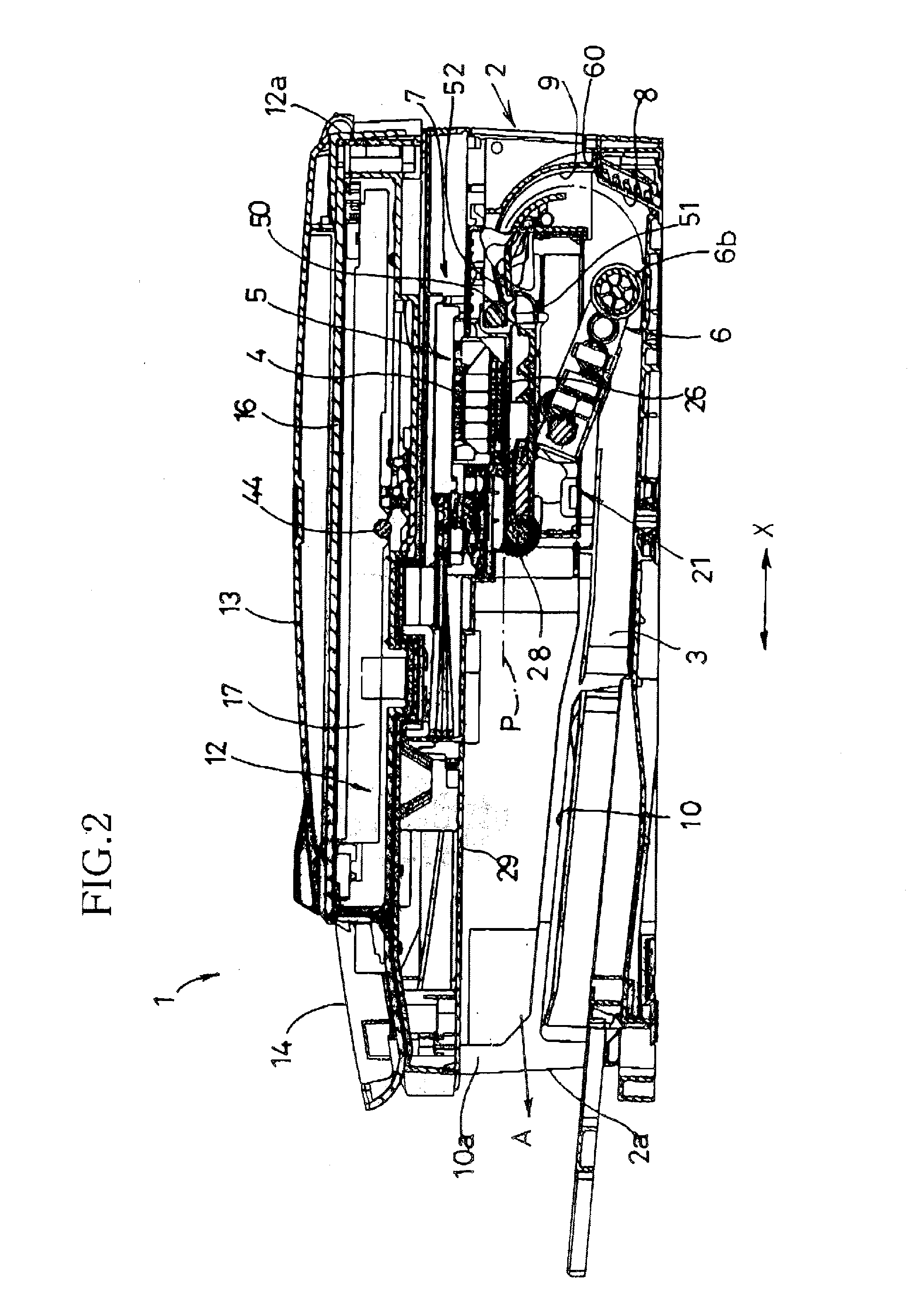
[0055] As shown in FIGS. 5 and 6, the sheet discharging roller 28 has a cylindrical shape having a diameter D1 and extending in the direction (the Y-axis direction or the widthwise direction of the sheet P) perpendicular to the sheet feeding direction A. The sheet discharging roller 28 is supported at its opposite axial end portions by the respective side plates 21a of the main frame 21 and is rotated by a drive force transmitted from the drive force. The sheet discharging roller 28 is made of a metal, and has an outer circumferential surface that is adapted to generate an increased friction force. For example, the outer circumferential surface of the sheet discharging roller 28 may be knurled, coated with ceramic particles by bonding, or fixedly covered with a rubber or ...

seventh embodiment

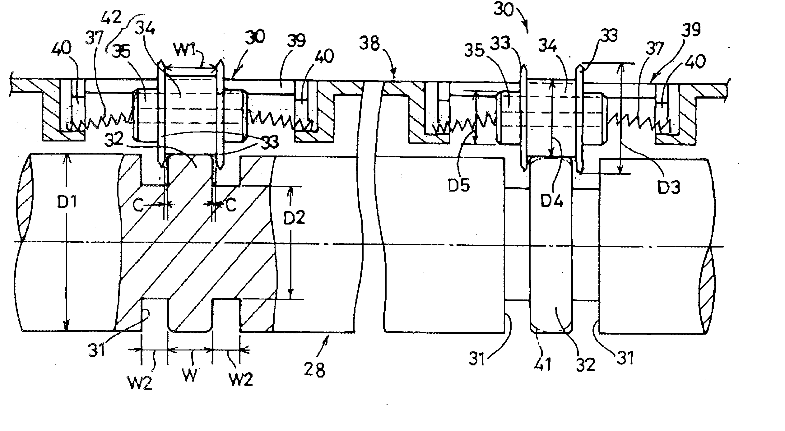
[0076]FIG. 17 shows a sheet holding structure according to the invention in which the driven roller is provided by a toothed wheel unit 730 including a single rowel 733 and two outside hub portions 735, while the drive roller is provided by a sheet discharging roller 728 including several pairs of non-grooved portions 732 and an annularly grooved portion 731 that is located between each adjacent pair of the non-grooved portions 732. In this embodiment, the outside hub portions 735 of the toothed wheel unit 730 serve as the contactable portion, while the non-grooved portions 732 of the sheet discharging roller 728 serve as the second portion. Thus, the outside hub portions 735 are held in contact with the non-grooved portions 732, during absence of the sheet between the toothed wheel unit 730 and the sheet discharging roller 728. The rowel 733 is distant from each of the non-grooved portions 732 by 1 mm or less as measured in the axial direction. Each of the non-grooved portions 732 ...

eighth embodiment

[0078]FIG. 19 shows a sheet holding structure according to the invention in which the driven roller is provided by a pair of toothed wheel units 730, while the drive roller is provided by a sheet discharging roller 828 including an annularly grooved portion 831. In this embodiment, a shaft 837 made of a rigid material is provided to extend through axial through-holes 736 of the toothed wheel units 730, such that the toothed wheel units 730 are rotatably mounted on the shaft 837. Further, in this embodiment, the biaser is provided by a pair of elastic members in the form of coil springs 740 each of which is connected at one of its opposite end portions to the support plate 38 and at the other end portion to a corresponding one of axial end portions of the shaft 837, so that the toothed wheel units 730 are biased toward the sheet discharging roller 828. As shown in FIG. 19, one of the outside hub portions 735 of each toothed wheel unit 730 serves as the contactable portion, while the ...


PUM

PropertyMeasurementUnit
lengthaaaaaaaaaa
axial lengthaaaaaaaaaa
widthaaaaaaaaaa

Abstract

A feeding device including a drive roller and a driven roller opposed to the drive roller and biased toward the drive roller, such that the drive and driven rollers cooperate to feed a sheet while holding the sheet therebetween. The driven roller includes a toothed wheel portion and a contactable portion having a diameter smaller than that of the toothed wheel portion. The drive roller includes first and second portions. A radially outer end of the second portion is more distant from an axis of the drive roller than a radially outer end of the first portion. During absence of the sheet between the drive and driven rollers, the contactable portion of the driven roller is held in contact at its circumferential surface with a circumferential surface of the second portion of the drive roller, while a radially outer end of the toothed wheel portion is not in contact with a circumferential surface of the first portion. Also disclosed is an image recording apparatus including the above-described feeding device.

Description

[0001] This application is based on Japanese Patent Application No. 2005-018127 filed in Jan. 26, 2005, the content of which is incorporated hereinto by reference. BACKGROUND OF THE INVENTION [0002] 1. Field of the Invention [0003] The present invention relates in general to a feeding device including: a drive roller that is driven by a drive source; and a driven roller that is opposed to the drive roller in its radial direction and is biased toward the drive roller, so that the drive and driven rollers cooperate with each other to feed a sheet in a feeding direction while holding the sheet therebetween. The invention also relates to an image recording apparatus equipped with such a feeding device. [0004] 2. Discussion of Related Art [0005] A feeding device for feeding a sheet is conventionally employed in an image recording apparatus of an inkjet type such as a printer, a facsimile machine or the like. In the sheet feeding device, it is desirable to feed the sheet without deteriora...

Claims


Application Information

Patent Timeline
Patent Type & Authority Applications(United States)
IPC IPC(8): B65H29/70B65H5/02
CPCB65H5/062B65H29/70B65H2301/5122B65H2404/1115B65H2404/141
Inventor IZUCHI, MASATOSHIITO, NORITSUGU
Owner BROTHER KOGYO KK
Why Eureka
Try Eureka