Vibration-type angular rate sensor

a technology of angular rate sensor and vibration, which is applied in the direction of acceleration measurement using interia force, turn-sensitive devices, instruments, etc., can solve the problems of increased manufacturing costs, increased processing costs, and inability to detect angular velocity accurately, so as to improve prevent the resonance point in the rotation mode from lowering, and secure the vibration-proof properties of the sensor chip

Inactive Publication Date: 2005-11-24
DENSO CORP
View PDF4 Cites 28 Cited by
  • Summary
  • Abstract
  • Description
  • Claims
  • Application Information

AI Technical Summary

Benefits of technology

[0012] According to the angular rate sensor of the present invention, it is preferable that the adhesive film consists of a plurality of adhesive film portions separately provided between the sensor chip and the circuit chip, and the plural adhesive film portions are symmetrically arranged about a rotation center of the oscillator in the sensor chip and are spaced from the rotation center. With this arrangement, it becomes possible to secure vibration-proof properties of the sensor chip and prevent the resonance point in the rotation mode from lowering. Furthermore, it becomes possible to assure appropriate detection sensitivity of angular velocity.
[0013] Furthermore, in order to accomplish the above and other related object, the present invention provides another angular rate sensor including a sensor chip, a circuit chip, and a package. The sensor chip, having an oscillator being driven to vibrate at a predetermined frequency, detects an angular velocity applied to the oscillator around a predetermined rotation axis. The circuit chip, being laminated with the sensor chip, has a circuit formed on a surface thereof to detect the angular velocity based on a signal obtained from the sensor chip. The package accommodates the circuit chip laminated with the sensor chip. The circuit chip and the package are bonded with an adhesive film. And, at least one of configuration or elastic coefficient of the adhesive film is adjusted to realize a condition that a resonance frequency of an integrated unit of the sensor chip and the circuit chip becomes smaller than a driving frequency of the oscillator. Even in such an arrangement, it becomes possible to improve the vibration-proof properties of the sensor chip.

Problems solved by technology

According to this kind of angular rate sensor, thermal stresses applied from the outside to the sensor chip and / or vibrations transmitted from the outside to the sensor chip give adverse effects on angular velocity detect accuracy of the sensor.
However, the sensor arrangement of the above-described prior art 1 is disadvantageous in that additional processing (or machining) is required to form a complicated surface of the package.
This will increase the manufacturing costs.
Furthermore, the bonding strength between the oscillator and the package tends to be incomplete.
This will deteriorate frequency characteristics of the entire sensor structure.
Furthermore, the above-described prior art 2 discloses nothing about vibration-proof properties of the angular rate sensor.
This will increase the costs.

Method used


Image

  • Vibration-type angular rate sensor
  • Vibration-type angular rate sensor
  • Vibration-type angular rate sensor

Examples


first embodiment

[0028] Hereinafter, a first embodiment of the present invention will be explained with reference to FIGS. 1 to 5.

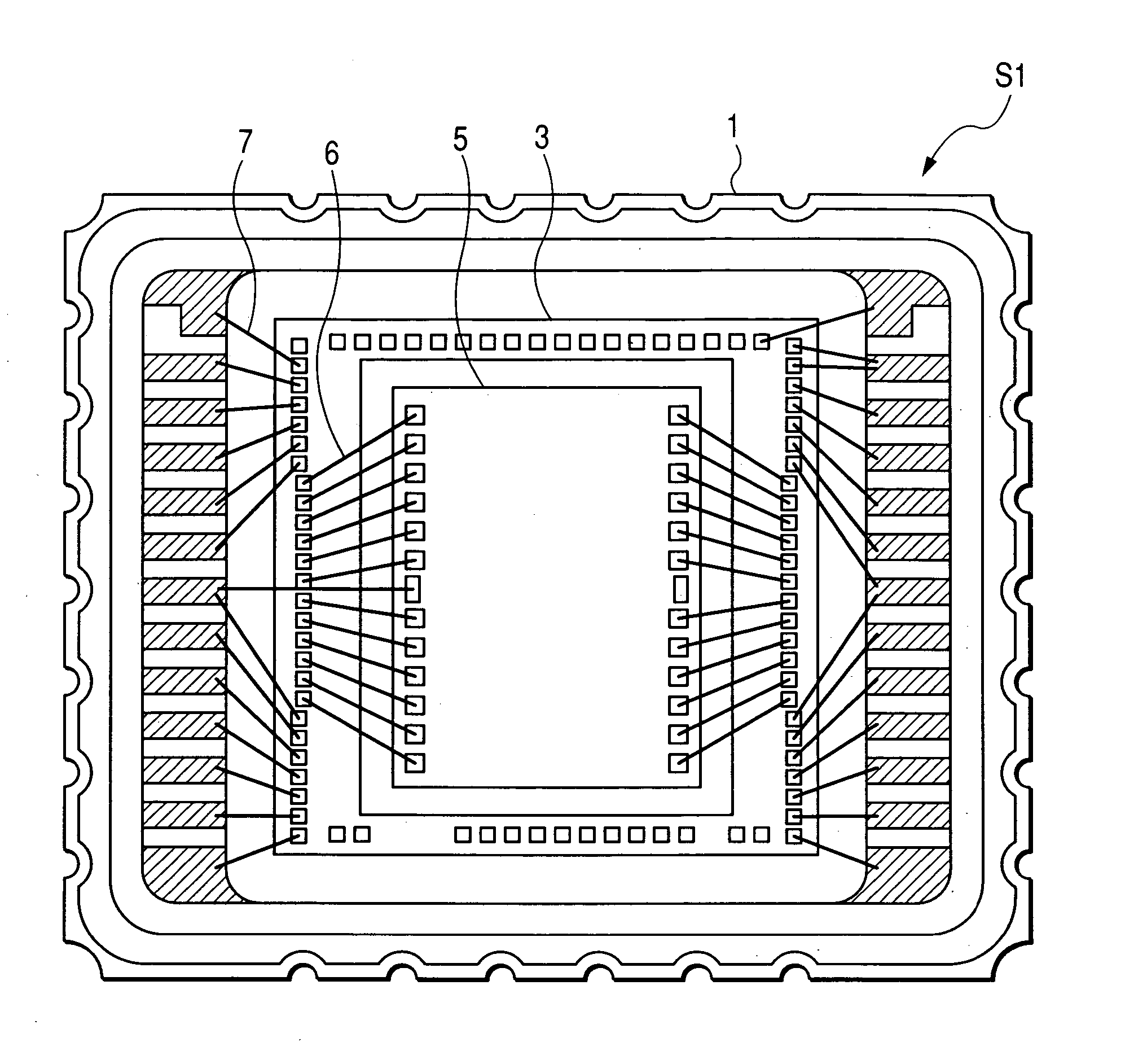
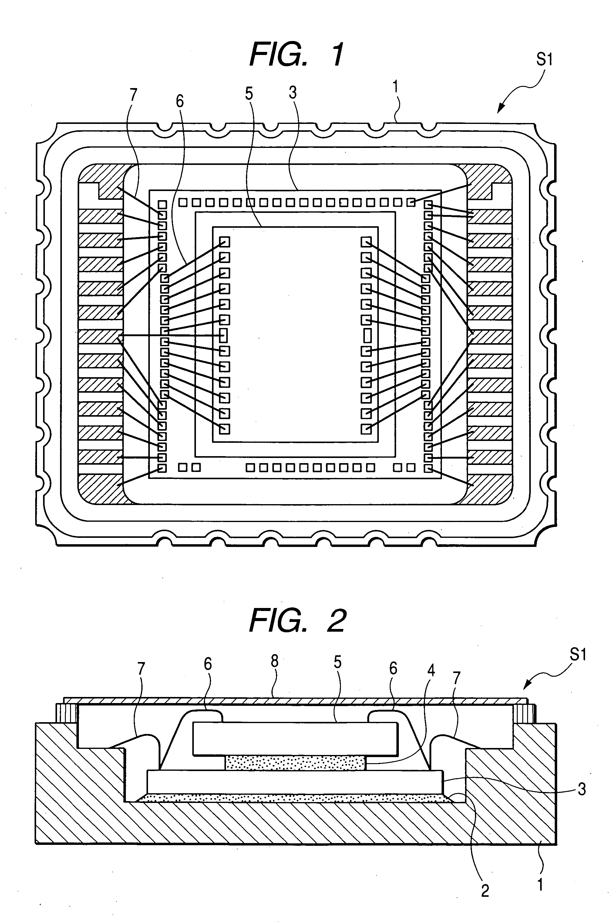
[0029]FIG. 1 is a plan view and FIG. 2 is a cross-sectional view, each showing an angular rate sensor S1 in accordance with a first embodiment of the present invention. As shown in FIGS. 1 and 2, the angular rate sensor S1 includes a ceramic package 1 which arranges a base portion of the sensor S1. The sensor S1 is attached to an appropriate portion of a member to be measured. A circuit chip 3 is mounted on a bottom of the ceramic package 1 and fixed there with an adhesive 2.

[0030] A boding portion, defining a region where the sensor chip 5 is mounted, is provided on an upper surface of the circuit chip 3. A sensor chip 5 is laminated on this boding portion via an adhesive film 4. According to this embodiment, the adhesive film 4 is a silicone-group film which has lower elasticity and appropriate viscoelastic characteristics.

[0031] The sensor chip 5 and the circuit chi...

second embodiment

[0046] Next, a second embodiment of the present invention will be explained with reference to FIGS. 6 to 9. The second embodiment is different from the above-described first embodiment in that adhesive film 4 is separated or divided into a plurality of adhesive film portions.

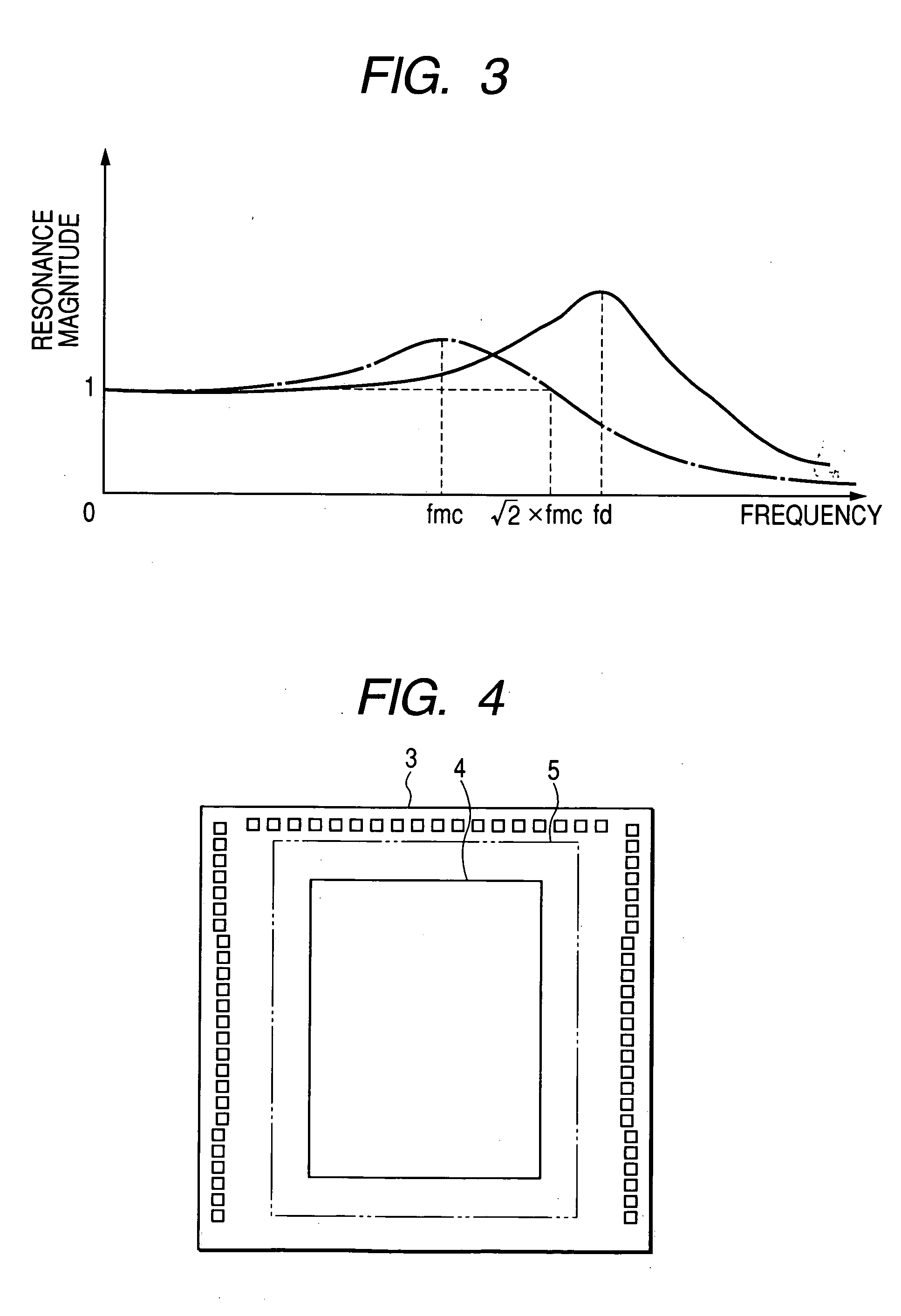
[0047] The above-described first embodiment can improve the vibration-proof properties. However, in the case that the area of adhesive film 4 is reduced at only one point corresponding to the central region of the sensor chip 5, the resonance point of the rotation mode in the sensor chip 5 will decrease. More specifically, when an angular velocity is applied around a rotation axis, the rotational force is transmitted along the route of package 1→circuit chip 3→sensor chip 5. In the case that reducing the area of the adhesive film 4 is performed at only one point corresponding to the central region of the sensor chip 5, the bonding portion between the circuit chip 3 and the sensor chip 5 is positioned closely to...

third embodiment

[0053] Next, a third embodiment of the present invention will be explained with reference to FIGS. 10 and 11. The third embodiment is different from the above-described first embodiment in that the sensor chip 5 includes two oscillators.

[0054]FIGS. 10 and 11 are plan views showing practical examples of plural adhesive film portions 4a and 4b formed on a circuit chip in accordance with a third embodiment of the present invention. According to the third embodiment of the present invention, the sensor chip 5 has two dissected oscillators 5a and 5b disposed in such a manner that their acceleration detecting sensitivities can be cancelled. From the view point of relaxing the thermal stresses acting on respective oscillators 5a and 5b, two adhesive film portions 4a and 4b are bonded so as to agree at their centers with the rotation axes (i.e. Z axes) of respective oscillators 5a and 5b as shown in FIGS. 10 and 11. According to this arrangement, the thermal stresses acting on respective o...


PUM


Abstract

An angular rate sensor includes a sensor chip having an oscillator vibrating at a predetermined frequency and detecting an angular velocity applied to this oscillator around a predetermined rotation axis. A circuit chip, laminated with the sensor chip, has a circuit formed on a surface thereof to detect the angular velocity based on a signal obtained from the sensor chip. The sensor chip and the circuit chip are bonded with an adhesive film. A resonance frequency of the sensor chip is smaller than (½)1/2 times a driving frequency of the oscillator in a condition that adjustment is applied to at least one of configuration or elastic coefficient of the adhesive film.

Description

CROSS-REFERENCE TO RELATED APPLICATION [0001] This application is based upon and claims the benefit of priority from earlier Japanese Patent Application No. 2004-147623 filed on May 18, 2004 so that the description of which is incorporated herein by reference. BACKGROUND OF THE INVENTION [0002] The present invention relates to a vibration-type angular rate sensor which drives and vibrates an oscillator to detect an angular velocity. [0003] The vibration-type angular rate sensor is, for example, formed by etching a semiconductor substrate to form a base portion, an oscillator, and drive electrodes of this oscillator. According to this kind of angular rate sensor, alternating-current signals (i.e. drive signals) having mutually opposite phases are applied to a pair of drive electrodes to cause the oscillator to vibrate in the predetermined direction. If any angular velocity is applied in a condition that the oscillator vibrates regularly in the predetermined direction, the oscillator ...

Claims


Application Information

Patent Timeline
Patent Type & Authority Applications(United States)
IPC IPC(8): G01C19/56G01C19/5719G01C19/5769G01P15/08
CPCG01C19/5719H01L2224/05554H01L2224/32145H01L2224/32225H01L2224/48145H01L2224/48227H01L2224/73265H01L2924/00H01L2924/00012
Inventor OHTA, TAMEHARU
Owner DENSO CORP
Why Eureka
Try Eureka