Female snap button

a technology of snap button and female, which is applied in the direction of snap fasteners, buckles, mechanical equipment, etc., can solve the problems of increased force required to mate and demate the projection with and from the projection-receiving space, high precision, and inability to produce female snaps. achieve the effect of promoting the difference in flexibility, high precision and easy production

Active Publication Date: 2013-10-22
YKK CORP
View PDF28 Cites 27 Cited by
  • Summary
  • Abstract
  • Description
  • Claims
  • Application Information

AI Technical Summary

Benefits of technology

[0012]In an embodiment of the invention, in the radially inner end of the inner bulge, parts corresponding to the thin-walled portions are slightly recessed radially outward rather than parts corresponding to the thick-walled portions. That is, in the radially inner end of the inner bulge, parts corresponding to the thin-walled portions are slightly recessed radially outward while parts corresponding to the thick-walled portions are relatively slightly swell radially inward. Such circumferentially alternate minute recesses and swells on the radially inner end of the inner bulge can help promote the difference in the flexibility between the thick-walled portions and the thin-walled portions.
[0013]In the invention, since the thick-walled portions and the thin-walled portions are provided alternately in the circumferential direction in the annular protrusion defining the projection-receiving space to mate with and demate from the projection of a male snap button, the flexibility of the annular protrusion changes alternately high to low in the circumferential direction. Therefore, high precision in terms of the flexibility of the annular protrusion is not required in producing the female snap, making the production easier. Further, a detachment resistance in the projection-receiving space relative to the projection can be maintained relatively high by the thick-walled portions as being low flexible, and a mating and demating force required to mate and demate the projection with and from the projection-receiving space can be reduced by the thin-walled portions as being high flexible. Furthermore, since the flexibility of the annular protrusion changes in the circumferential direction, it is unlikely to bring about nonuniformity in the detachment resistance or the mating and demating force in the circumferential direction.

Problems solved by technology

For this reason, very high precision is required for the flexibility of the annular protrusion, so it is not easy to produce female snaps.
Further, to enhance a resistance in the projection-receiving space to detachment from the projection, there is a problem that a force required to mate and demate the projection with and from the projection-receiving space will be increased.
In addition, because of faulty molding or long-term use, there would be nonuniformity in the detachment resistance or the mating and demating force in the circumferential direction such that the projection would be easily removed from the projection-receiving space at a certain point in the circumferential direction.[Patent document 1] Japanese Examined Utility Model Application Publication No.

Method used


Image

  • Female snap button
  • Female snap button
  • Female snap button

Examples


Embodiment Construction

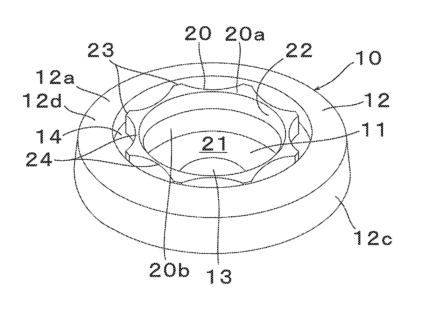
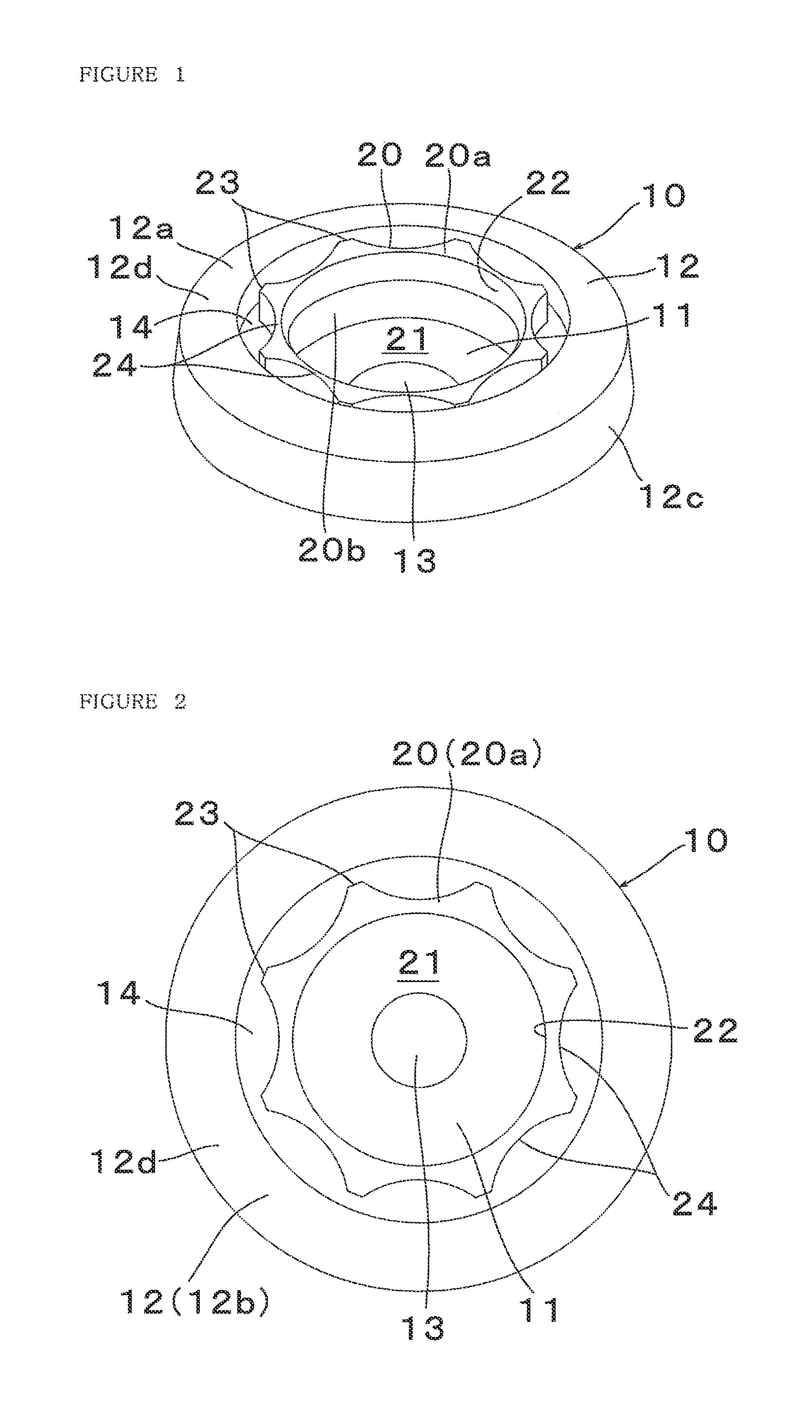
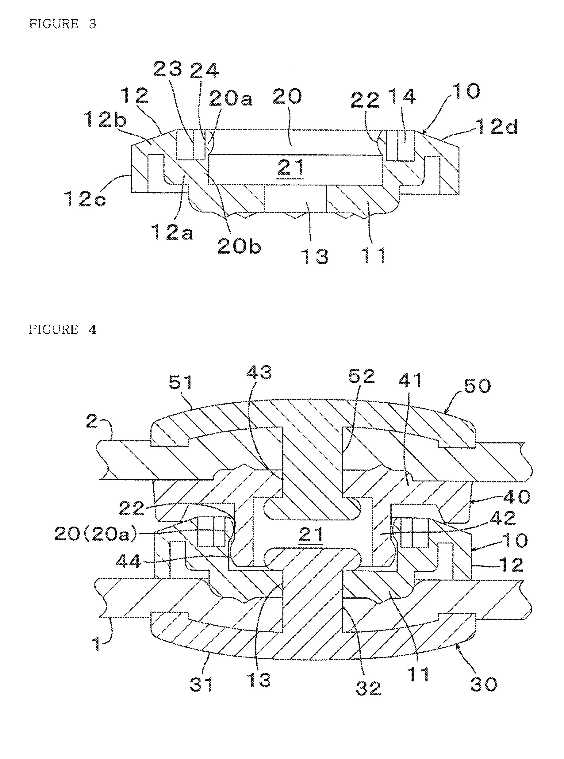
[0025]Hereinafter, preferred embodiments of the present invention be described with reference to the drawings. FIGS. 1 to 3 are a perspective view, a plan (top) view and a longitudinal sectional view, respectively, of a female snap button (hereinafter referred to simply as “female snap”) 10 in accordance with an embodiment of the invention. The female snap button 10 is injection-molded of thermoplastic resin and comprises a disk-like base 11, an annular protrusion 20 rising upward (up-and-down directions are based on FIG. 3) from a radially outer end of the base 11, and a flange 12 extending radially outward from a lower half portion 20b of the annular protrusion 20. In a center part of the base 11, there is formed a through-hole 13 to pass a post 32 of a button fastener 30 (see FIG. 4) through the hole when the female snap 10 become fastened to a cloth 1 (see FIG. 4). The annular protrusion 20 defines radially inward above the base 11 a projection-receiving space 21 for detachably ...


PUM

PropertyMeasurementUnit
thicknessaaaaaaaaaa
flexibilityaaaaaaaaaa
elasticityaaaaaaaaaa

Abstract

A female snap button detachably receives a projection of a male snap button in a projection-receiving space. The female snap button includes an annular protrusion rising from a base and defining the projection-receiving space. In the annular protrusion, there are formed thick-walled portions with the thickness from the inner surface of the protrusion to the radially outer side being relatively thick and thin-walled portions with the thickness being thinner than that in the thick-walled portions. The thick-walled portions and the thin-walled portions are arranged alternately in the circumferential direction.

Description

[0001]This application is a national stage application of PCT / JP2010 / 051521 which is incorporated herein by reference.BACKGROUND OF THE INVENTION[0002]The present invention relates to a female snap button, and especially to a female snap button made of synthetic resin.[0003]A snap button, which is widely used for parts to be put together of clothing etc., consists of a male snap button (male snap) as fixed to one of the clothing parts and a female snap button (female snap) fixed to the other. The male and female snaps are connected and disconnected with each other by mating and demating a projection of the male snap with and from a projection-receiving space of the female snap. A female snap made of synthetic resin can obtain flexibility (elasticity) more easily than a metal snap for mating and demating the projection with and from the projection-receiving space. A female snap as injection-molded of thermoplastic resin is disclosed in e.g. Japanese Examined Utility Model Application...

Claims


Application Information

Patent Timeline
Patent Type & Authority Patents(United States)
IPC IPC(8): A44B1/18
CPCA44B17/0023A44B17/0029A44B17/0052A44B17/0076Y10T24/3685Y10T24/45225Y10T24/366Y10T24/3683
Inventor HASEGAWA, KENJIMOMOSE, MAKOTOSUGIYAMA, HIROYUKI
Owner YKK CORP
Why Eureka
Try Eureka