Image forming system

Active Publication Date: 2018-06-21
KONICA MINOLTA INC
View PDF0 Cites 1 Cited by
  • Summary
  • Abstract
  • Description
  • Claims
  • Application Information

AI Technical Summary

Benefits of technology

[0010]The present invention is made in view of the above problem. Accordingly, the objects of the present invention are to provide the image forming system that, even if the information on the paper conveyance is

Problems solved by technology

However, between the upstream apparatus and the downstream apparatus, by unpredictable factors such as the friction between the paper and the paper conveying path and the slipping of the paper relative to the conveying roller, a delay may occur to the paper which is conveyed from the upstream apparatus to the downstream apparatus.
On the other hand, in the image forming system including the upstream apparatus and the downstream apparatus, since a configuration for exchanging the information on the paper conveyance is not provided between the upstream apparatus and the downstream apparatus, the downstream apparatus may not acquire the information on the paper conveyance at the upstream apparatus.
Although it is possible to newly add a configuration for exchanging the information on the paper conveyance between the upstream apparatus and the downstream apparatus, it is possible that the significant cost occurs and it is not realistic.
As described above, in the im

Method used


Image

  • Image forming system
  • Image forming system
  • Image forming system

Examples


first embodiment

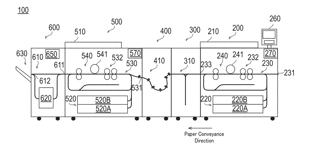
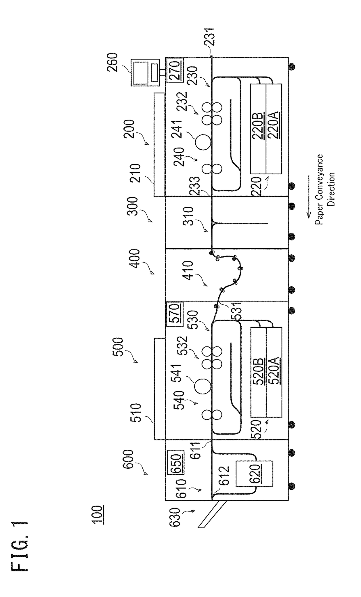
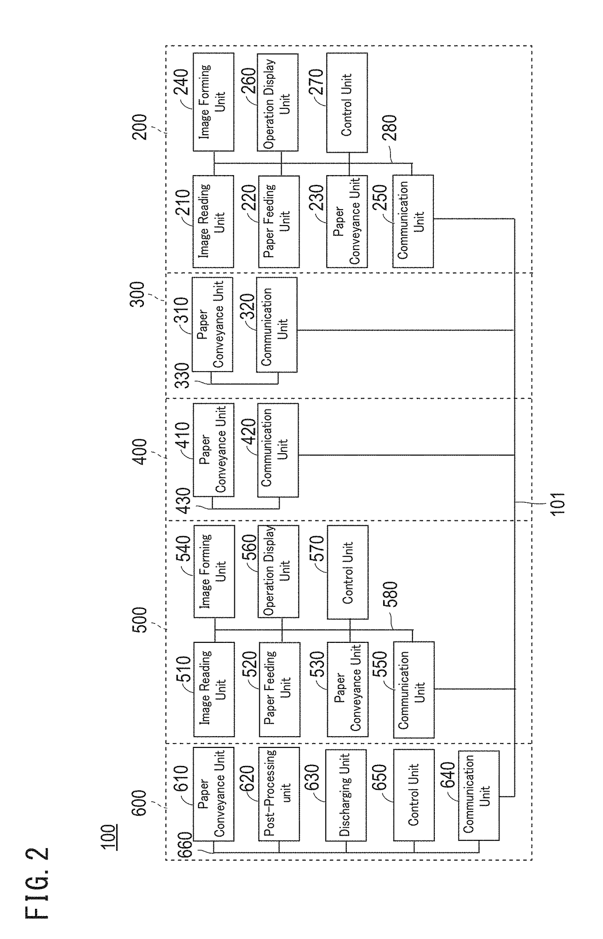
[0034]FIG. 1 is a schematic cross-sectional view exemplifying a configuration of the image forming system according to the first embodiment and FIG. 2 is a schematic block diagram exemplifying a configuration of the image forming system illustrated in FIG. 1. Further, FIG. 3 is a schematic diagram exemplifying a configuration of the resist unit of the upstream apparatus illustrated in FIG. 1 and FIG. 4 is a schematic diagram exemplifying the creation of the resist loop at the resist unit illustrated in FIG. 3.

[0035]100>

[0036]As illustrated in FIG. 1, an image forming system 100 includes an upstream apparatus 200, a first intermediate conveying device 300, a second intermediate conveying device 400, a downstream apparatus 500, and a post-processing device 600, all of which are connected in series along the paper conveyance direction. The upstream apparatus 200 and the downstream apparatus 500 operate as the image forming apparatus of the series tandem system.

[0037]In the image formin...

second embodiment

[0145]In the first embodiment, descriptions are given for a case in which resuming of the conveyance of the following paper whose conveyance is stopped at the resist unit is advanced and thus, the delay time of the following paper is solved or reduced. In the second embodiment, descriptions are given for a case in which, in the second intermediate conveying device, the conveyance speed of the following paper is increased to solve or reduce the delay time of the following paper. To avoid the duplication of descriptions, for configurations which are the same as those of the first embodiment, detailed descriptions are omitted.

[0146]The downstream apparatus of the present embodiment can include configurations of the downstream apparatus of the first embodiment. For example, the downstream apparatus of the present embodiment may include or not include a configuration for advancing resuming of the conveyance of the following paper Sn whose conveyance is stopped at the resist unit of the f...


PUM


Abstract

An image forming system includes a first device and a second device that are connected in series. The first device can continuously discharge a paper. The second device is blocked from information on a paper conveyance in the first device. The second device, based on printing setting information and a time at which the first paper passes the predetermined position, sets a printing cycle, and based on a time at which the second paper passes the predetermined position, calculates a delay time from a printing cycle of the second paper. The second device stops a conveyance of the second paper that is conveyed to the paper processor, and in accordance with the delay time, controls resuming of the stopped conveyance of the second paper.

Description

CROSS-REFERENCE TO RELATED APPLICATION[0001]The present invention claims priority under 35 U.S.C. § 119 to Japanese Patent Application No. 2016-245743, filed on Dec. 19, 2016, the entire contents of which is incorporated herein by reference.BACKGROUND1. Technological Field[0002]The present invention relates to an image forming system.2. Description of the Related Art[0003]In recent years, in the field of the production print (hereinafter, also referred to as “PP”), a technique for increasing the speed and enhancing the efficiency of the printing process has been developed. As one of the techniques for increasing the speed and enhancing the efficiency of the printing process, it is generally known an image forming apparatus of a series tandem system obtained by connecting two image forming apparatus which are operable alone in series. In the present description, among the image forming apparatuses of the series tandem system, an image forming apparatus located at an upstream side in ...

Claims


Application Information

Patent Timeline
IPC IPC(8): G03G15/00
CPCG03G15/70G03G15/5008G03G15/55G03G15/602G03G15/238G03G2215/00341G03G15/6564G03G2215/00021B65H7/20
Inventor ISOHARA, HIDEO
Owner KONICA MINOLTA INC
Why Eureka
Try Eureka