Package-type air-cooled screw compressor
a screw compressor and screw body technology, applied in the direction of machines/engines, rotary/oscillating piston pump components, liquid fuel engines, etc., can solve the problems of leakage of built-in device noise to the outside of the package, the problem of how to satisfy both the cooling of built-in devices and the leakage suppression of built-in device noise, and achieve the effect of improving the cooling effect of the compressor body and leaking of noise propagated through the du
- Summary
- Abstract
- Description
- Claims
- Application Information
AI Technical Summary
Benefits of technology
Problems solved by technology
Method used
Image

Examples
embodiment 1
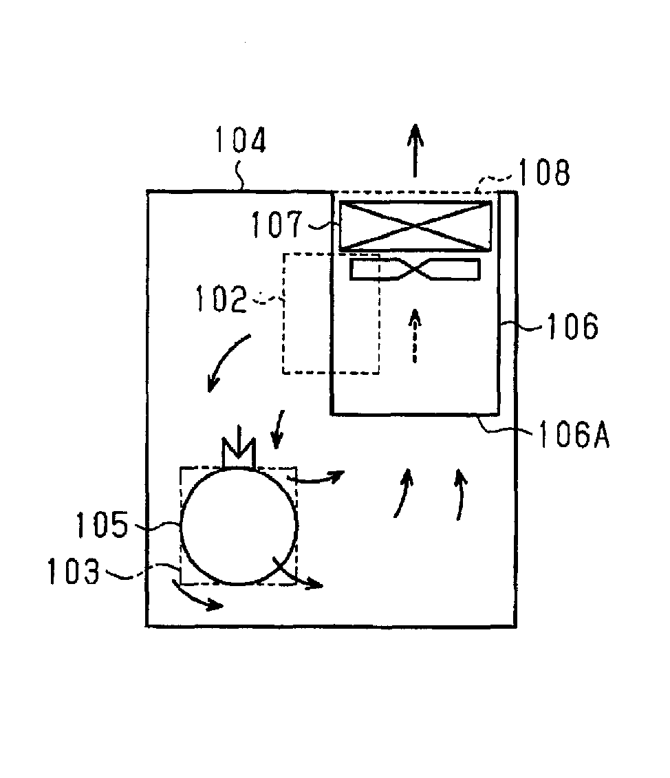
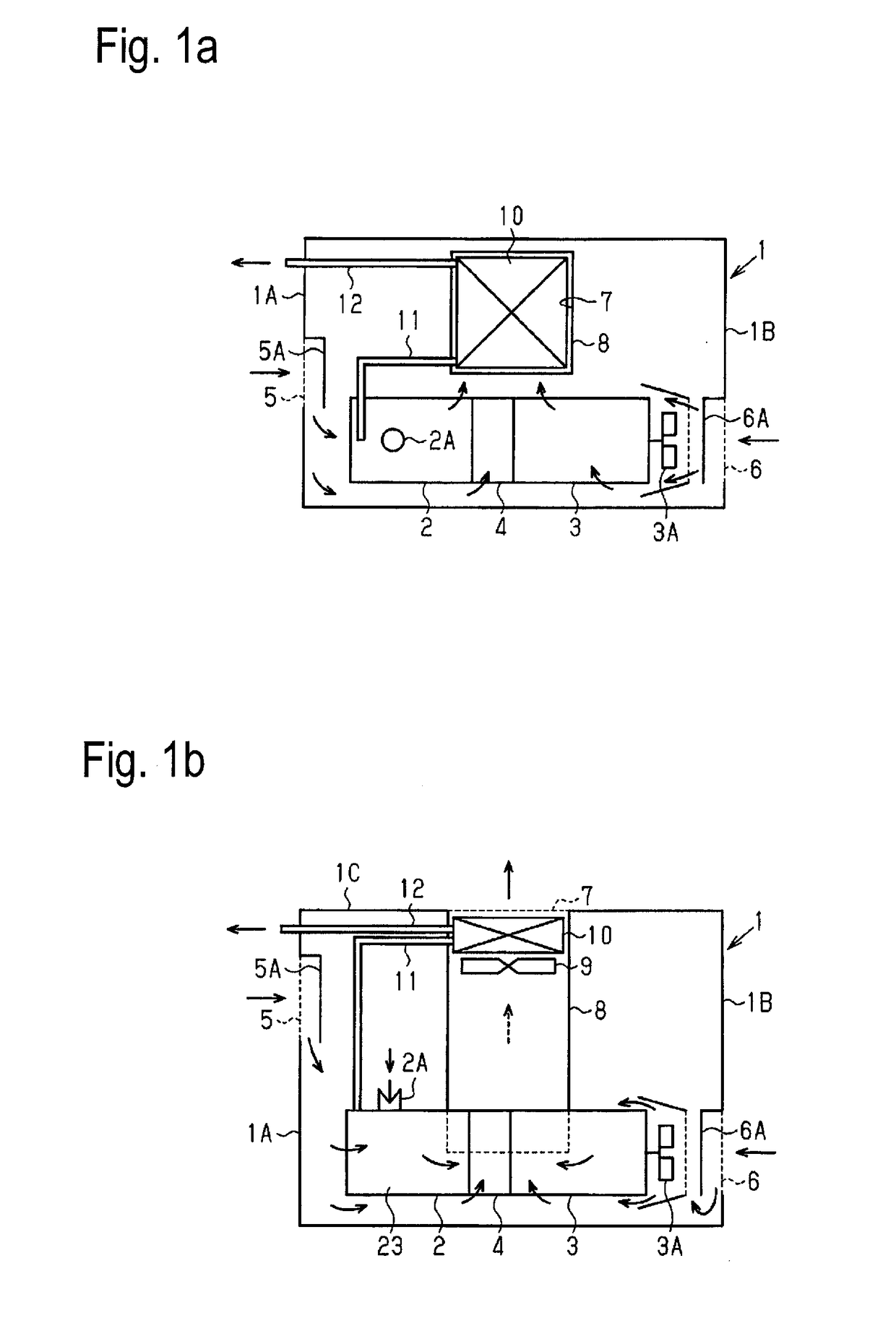
[0071]As illustrated in FIG. 1a, FIG. 1b and FIG. 1c, a package-type air-cooled screw compressor according to Embodiment 1 houses a compressor body 2 equipped with screw rotors for compression, a drive motor 3 for driving the compressor body 2, and a gear box 4 for connecting the compressor body 2 and the drive motor 3 inside a package 1.
[0072]In this Embodiment, the compressor body 2 is the main body of a screw compressor serving as an oil-cooled type in which lubricant oil is injected during a compression process and also serving as an air-cooled type in which compressed air and lubricant oil are cooled by cooling air. Furthermore, this screw compressor has an air intake port 2A for sucking in air for compression subjected to compression at the upper section of the casing of the compressor body 2. In addition, the air intake port 2A is provided with a throttle valve. The present invention is applicable to not only the above-mentioned oil-cooled type but also an air-cooled screw co...
embodiment 2
[0113]Next, Embodiment 2 will be described on the basis of FIG. 3a to FIG. 3d.
[0114]In Embodiment 2, the lower ends of the front wall 81 and the left side wall 82 of the hanging wall faces constituting the cooling duct 8 in Embodiment 1 are changed. In Embodiment 2, the same components as those in Embodiment 1 are designated by the same reference signs and their descriptions are omitted. This point is similarly applicable to the descriptions of Embodiment 3 and the following embodiments.
[0115]In other words, as illustrated in FIG. 3d, the lowest point P1 of the corner sections of the front wall 81 and the left side wall 82 is the same as in the case of Embodiment 1. Furthermore, the lower end of the front wall 81 is formed as an inclined side into a shape rising from the lowest point P1 to the lower end point P2 on the front side of the right side wall 83. Moreover, the lower end of the left side wall 82 is formed as an inclined side into a shape rising from the lowest point P1 to ...
embodiment 3
[0119]Next, Embodiment 3 will be described on the basis of FIG. 4a to FIG. 4d.
[0120]Embodiment 3 is different from Embodiment 1 in the position of the exhaust opening 7; since the cooling duct 8 is disposed so as not to be extended directly downward from the exhaust opening 7, the hanging wall faces of the cooling duct 8 are changed so as to conform to this disposition condition.
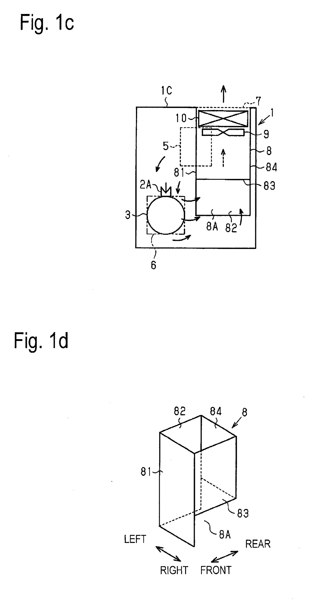
[0121]As can be fully seen from FIG. 4a to FIG. 4c, in this embodiment, since the exhaust opening 7 is formed in the center section of the top plate 1C in the front-rear direction, if made to hang directly downward, the lower sections of the front wall 81 and the left side wall 82 of the cooling duct 8 interfere with the compressor body 2, the gear box 4 and the drive motor 3. Hence, in Embodiment 3, the lower section of the cooling duct 8 is bent to the rear side of the compressor body 2 and the like to avoid this interference.
[0122]Also in this case, the lower ends of the front wall 81 and the left side w...
PUM
 Abstract
Description
Claims
Application Information
 - R&D
- Intellectual Property
- Life Sciences
- Materials
- Tech Scout
- Unparalleled Data Quality
- Higher Quality Content
- 60% Fewer Hallucinations
Browse by: Latest US Patents, China's latest patents, Technical Efficacy Thesaurus, Application Domain, Technology Topic, Popular Technical Reports.
© 2025 PatSnap. All rights reserved.Legal|Privacy policy|Modern Slavery Act Transparency Statement|Sitemap|About US| Contact US: help@patsnap.com