Magnetron having specific dimensions for solving noise problem
- Summary
- Abstract
- Description
- Claims
- Application Information
AI Technical Summary
Benefits of technology
Problems solved by technology
Method used
Image


Examples
Embodiment Construction
A magnetron according to an embodiment of the present invention will now be described in detail with reference to accompanying drawings.
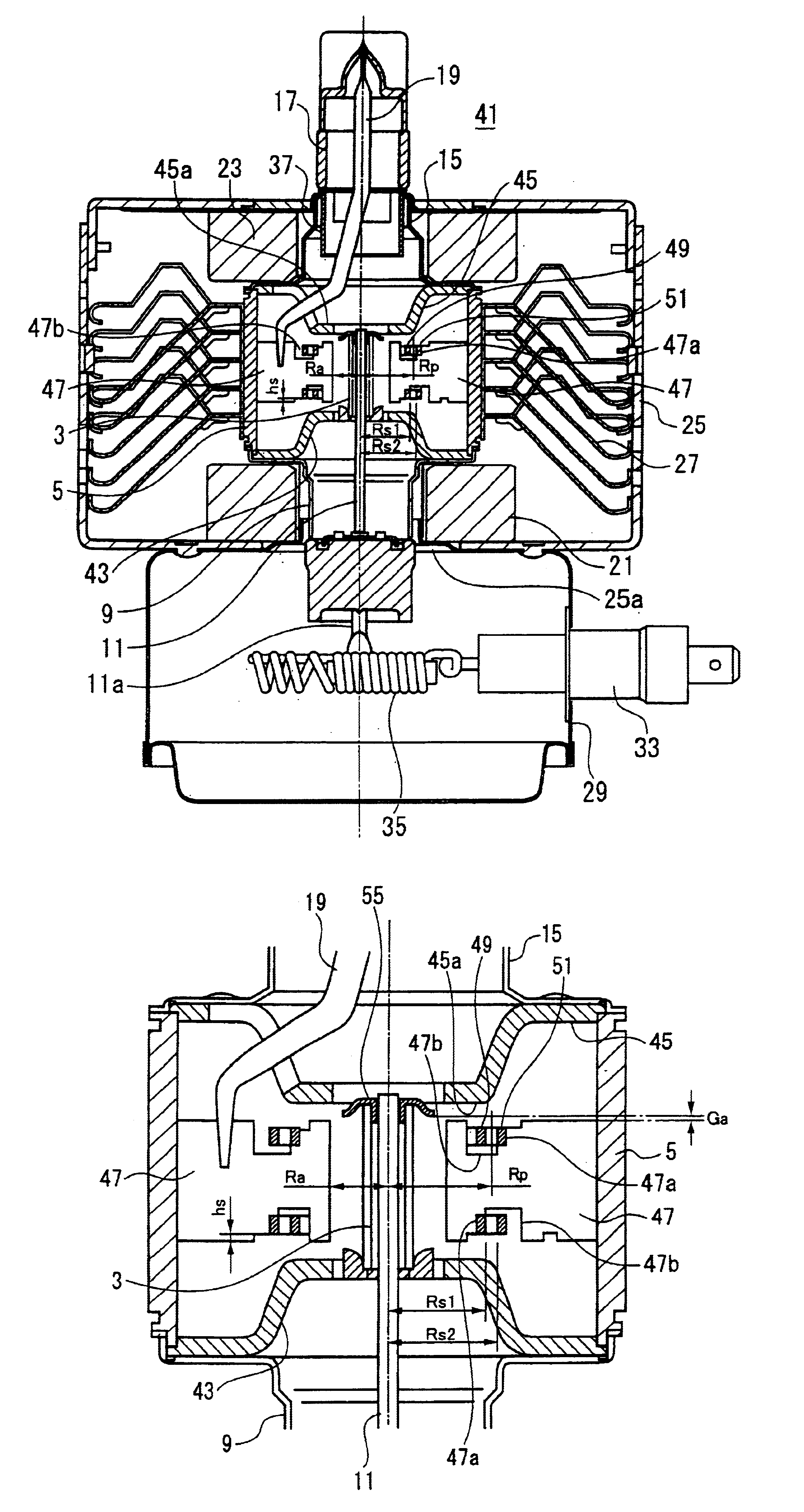
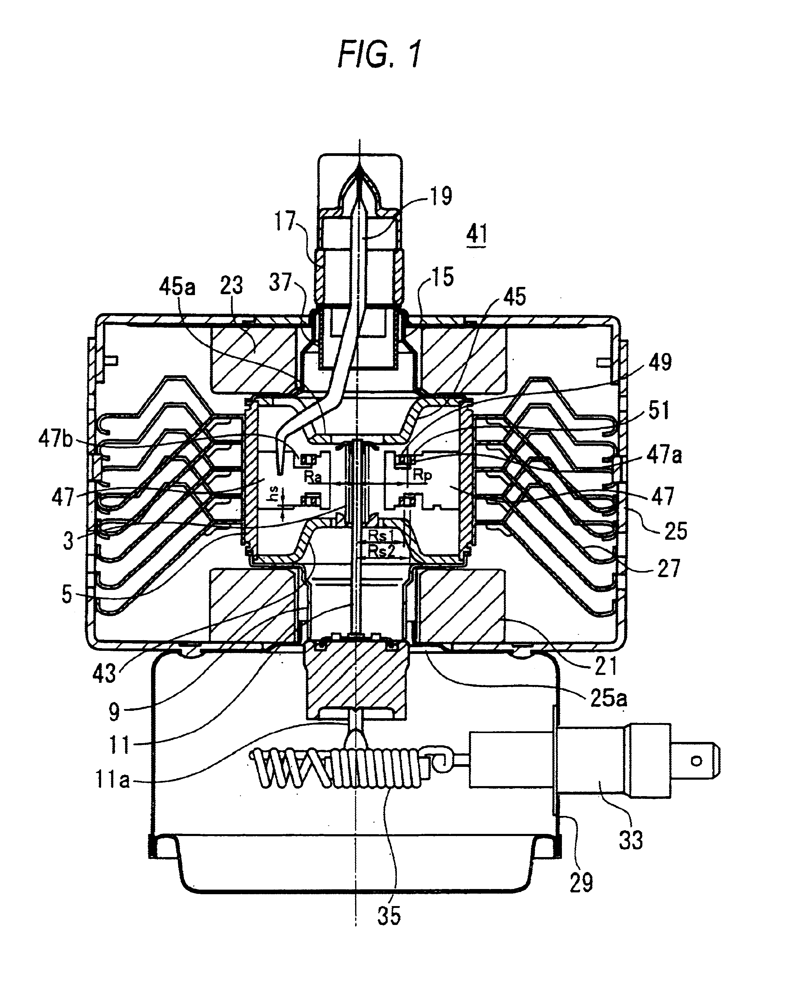
FIG. 1 is a cross-sectional diagram for indicating a magnetron 41 according to an embodiment of the present invention.
The magnetron 41 of this embodiment is constructed by replacing the input-sided magnetic piece 7 of the conventional magnetron 1 shown in FIG. 11 by an input-sided magnetic piece 43; the output-sided magnetic piece 13 there of by an output-sided magnetic piece 45; the anode vanes 20 thereof by anode vanes 47; the small-diameter strap ring 22 thereof by a small-diameter strap ring 49; and also the large-diameter strap ring 24 by a large-diameter strap ring 51. Other structures of this magnetron 41 are commonly used as those of the convential magnetron 1. It should be noted that the same reference numerals shown in FIG. 11 are employed as those for denoting these commonly-used structural elements, and therefore, explanations thereof ar...
PUM
 Abstract
Description
Claims
Application Information
 - R&D
- Intellectual Property
- Life Sciences
- Materials
- Tech Scout
- Unparalleled Data Quality
- Higher Quality Content
- 60% Fewer Hallucinations
Browse by: Latest US Patents, China's latest patents, Technical Efficacy Thesaurus, Application Domain, Technology Topic, Popular Technical Reports.
© 2025 PatSnap. All rights reserved.Legal|Privacy policy|Modern Slavery Act Transparency Statement|Sitemap|About US| Contact US: help@patsnap.com