Display apparatus

a technology of display apparatus and display screen, which is applied in the direction of electrical apparatus casing/cabinet/drawer, mechanical vibration separation, transducer diaphragm, etc., can solve the problems of reducing the correlation between the image and the vibration, reducing the immersion level of the viewer, and reducing the realism of the image, so as to increase the immersion level of the viewer. , the effect of reducing the immersion level

Active Publication Date: 2018-07-12
LG ELECTRONICS INC
View PDF2 Cites 22 Cited by
  • Summary
  • Abstract
  • Description
  • Claims
  • Application Information

AI Technical Summary

Benefits of technology

[0011]The prior art has a problem in that the realism of an image is degraded due to a long distance between a sound generation position in the image that a viewer visually recognizes (e.g. a person's mouth in the image) and a position from which a sound that the viewer acoustically perceives comes (a sound image). It is a second object of the present invention to solve this problem with the prior art and to minimize the distance between the visual sound generation position and the acoustical sound generation position.
[0012]In the prior art, when a user touches a display panel of a display apparatus, which is put in a case, to generate vibration (for example, when a user grabs a smartphone with one hand and touches a display panel of the smartphone with the other hand), the magnitude of the tactile vibration that the user feels at the contact point between the display panel and the user is smaller than the magnitude of the tactile vibration that the user feels at the contact point between the case and the user. Therefore, the prior art has a problem in that the correlation between the image and the vibration is reduced and a disconnect between the image and the vibration occurs. It is a third object of the present invention to solve this problem with the prior art and to minimize the distance between the visual vibration generation position (the position of the image) and the tactile vibration generation position.
[0015]It is a sixth object of the present invention to further increase the magnitude of the vibration output in the low frequency range for a given applied voltage.
[0016]It is a seventh object of the present invention to prevent the reduction of the efficiency of the vibration output in the high frequency range or to increase the efficiency of the vibration output in the high frequency range while accomplishing the above objects.
[0017]It is an eighth object of the present invention to minimize the thickness of the display apparatus in the front-rear direction while accomplishing the above objects.
[0019]It is a tenth object of the present invention to provide a display apparatus having a neat appearance, improved durability and excellent efficiency of sound output while accomplishing at least some of the above objects.

Problems solved by technology

The prior art has a problem in that the immersion level of a viewer is decreased due to a gap between a display panel for outputting images and a position at which vibration is generated by a vibration device.
The prior art has a problem in that the realism of an image is degraded due to a long distance between a sound generation position in the image that a viewer visually recognizes (e.g. a person's mouth in the image) and a position from which a sound that the viewer acoustically perceives comes (a sound image).
Therefore, the prior art has a problem in that the correlation between the image and the vibration is reduced and a disconnect between the image and the vibration occurs.
The prior art has a problem in that the magnitude of the output in the low frequency range of the piezoelectric vibration device is relatively small.

Method used


Image

  • Display apparatus
  • Display apparatus
  • Display apparatus

Examples


first embodiment

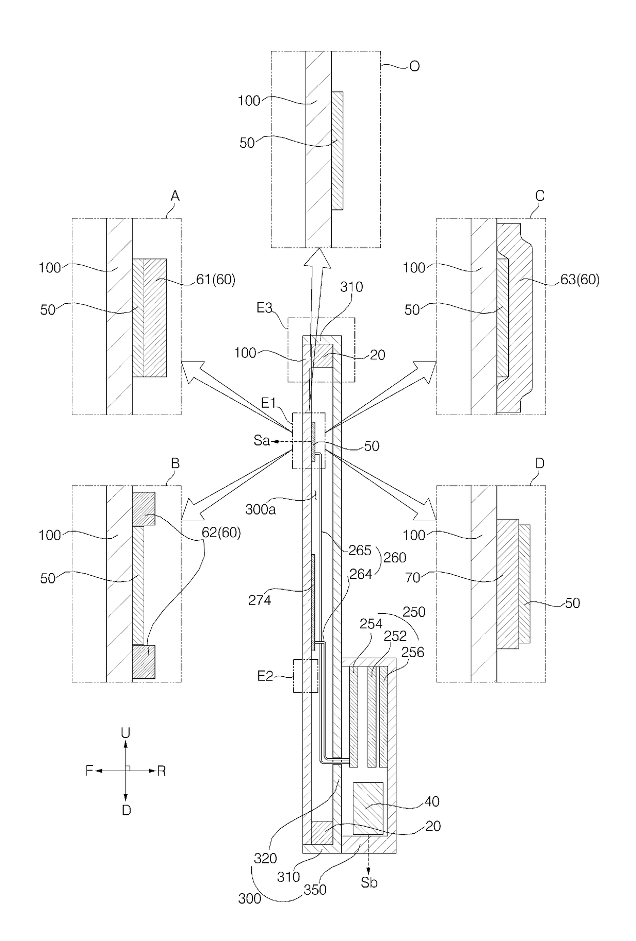
[0079]A side cover 311, illustrated in FIG. 8a, may be supported by hardening a semisolid sealing material. The side cover 311 may be attached to one surface of the adhesive sheet 20 along the periphery of the display panel 100 in a sealed manner. The sealing material is hardened in the state of being in contact with the periphery of the display panel 100, the periphery of the back cover 320 and the one surface of the adhesive sheet 20, with the result that the side cover 311 is securely supported.

second embodiment

[0080]A side cover 312, illustrated in FIG. 8b, may be fixedly inserted into a gap between the rear surface of the display panel 100 and the front surface of the back cover 320. The side cover 312 is disposed in contact with one surface of the adhesive sheet 20. One end of the side cover 312 is in contact with the one surface of the adhesive sheet 20, and the other end of the side cover 312 is bent in the forward direction. The side end of the display panel 100 is shielded by the side cover 312. The side end of the display panel 100 may be in contact with the side cover 312.

third embodiment

[0081]A side cover 313, illustrated in FIG. 8c, may be fixedly inserted into a gap between the rear surface of the display panel 100 and the front surface of the back cover 320. The side cover 313 is disposed so as to be spaced apart from one surface of the adhesive sheet 20. The side cover 313 includes an insertion portion 313a, which is inserted into a gap between the rear surface of the display panel 100 and the front surface of the back cover 320. A portion of the side cover 313 protrudes from the insertion portion 313a in the forward direction and shields the side end of the display panel 100. The side end of the display panel 100 may be in contact with the side cover 313. A portion of the side cover 313 protrudes from the insertion portion 313a in the backward direction and shields the side end of the back cover 320. The side end of the back cover 320 may be in contact with the side cover 313.


PUM


Abstract

A display apparatus is disclosed. The display apparatus includes a display panel, a piezoelectric vibration unit attached to a rear surface of the display panel, and a member attached to at least one of a rear surface of the piezoelectric vibration unit and a portion of the rear surface of the display panel that surrounds the piezoelectric vibration unit. The display apparatus includes a display panel, a damping member attached to a rear surface of the display panel, and a piezoelectric vibration unit attached to a rear surface of the damping member.

Description

CROSS-REFERENCE TO RELATED APPLICATION[0001]Pursuant to 35 U.S.C. § 119, this application claims the benefit of earlier filing date and right of priority to Korean Application No(s). 10-2017-0012502, filed on Jan. 26, 2017, and also claims the benefit of U.S. Provisional Application No. 62 / 418,809, filed on Nov. 8, 2016, the contents of which are all hereby incorporated by reference herein in their entirety.BACKGROUND OF THE INVENTION1. Field of the Invention[0002]The present invention relates to a display apparatus that generates vibration.2. Description of the Related Art[0003]There are various kinds of display panels for generating images, for example, liquid crystal displays (LCDs), plasma display panels (PDPs), electro-luminescent displays (ELDs), vacuum fluorescent displays (VFDs), organic light-emitting diode (OLED) displays, etc.[0004]A display apparatus, equipped with a display panel and a vibration unit for generating vibration, has been developed. The vibration unit refer...

Claims


Application Information

Patent Timeline
Patent Type & Authority Applications(United States)
IPC IPC(8): H01L41/09H05K5/00H01L41/187H01L41/053H05K5/03G06F3/01
CPCH01L41/09H05K5/0017G06F3/016H01L41/0533H05K5/03H01L41/1876B06B1/06G06F1/1605G06F1/1626G06F1/1637G06F1/1684G06F1/1688H04R17/00H04R1/26H04R2499/11H04R2499/15G06F3/01H04M1/0266H04M1/03H04R7/045H04R2400/03H04R2440/05H10N30/88H04R1/025H04R7/04H10N30/20H10N30/883H10N30/8554
Inventor PARK, JONGHA
Owner LG ELECTRONICS INC
Why Eureka
Try Eureka