
Image generation device, image generation system, and image generation method

a technology of image generation and image, applied in the field of image generation devices, can solve the problems of large distortion of image obtained by the entire peripheral photography, affecting the quality of peripheral images, and affecting the quality of peripheral images, and achieving the effect of reducing the difficulty of capturing the positional relationship of objects displayed on the entire peripheral imag

Inactive Publication Date: 2018-07-19
HITACHI INFORMATION & CONTROL SOLUTIONS LTD
View PDF2 Cites 4 Cited by
  • Summary
  • Abstract
  • Description
  • Claims
  • Application Information

AI Technical Summary

Benefits of technology

The invention makes it easy to see the entire peripheral image in virtual space. This helps to better understand the problem, configure the system and observe its effects.

Problems solved by technology

However, an image obtained by the entire peripheral photography has a large distortion and gives a sense of strangeness, and thus a method of presenting the image is not so simple compared to when an image obtained by an ordinary camera is displayed.
Such display results in a significant difficulty in grasping the positional relationship of objects displayed on entire peripheral images particularly when such entire peripheral images are captured at a plurality of positions.
Meanwhile, in order to reconstruct a complete three-dimensional model from a plurality of images, a large amount of images and depth information are required, and the reconstructed image often does not have enough reconstruction accuracy.
However, the map and the image are displayed on separate windows, resulting in a difficulty in grasping the relationship between a position indicated on the map and a viewpoint position on the image.
Further, when entire peripheral images captured at a plurality of positions are displayed in combination, it is difficult to intuitively grasp a relationship between the image and the map or a relationship between the images.
However, this technology displays only one panoramic image at a time, and does not consider displaying a plurality of panoramic images.

Method used


Image

  • Image generation device, image generation system, and image generation method
  • Image generation device, image generation system, and image generation method
  • Image generation device, image generation system, and image generation method

Examples


first embodiment

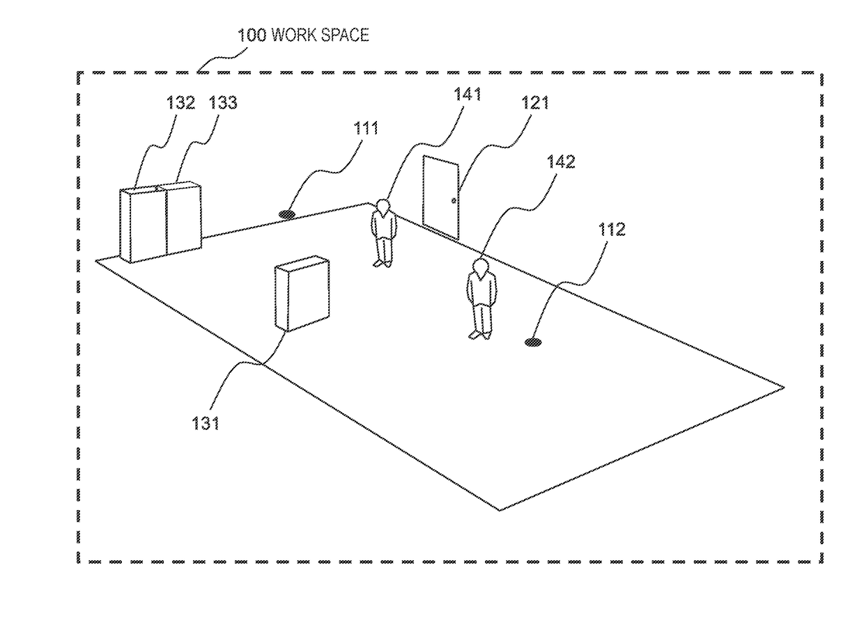
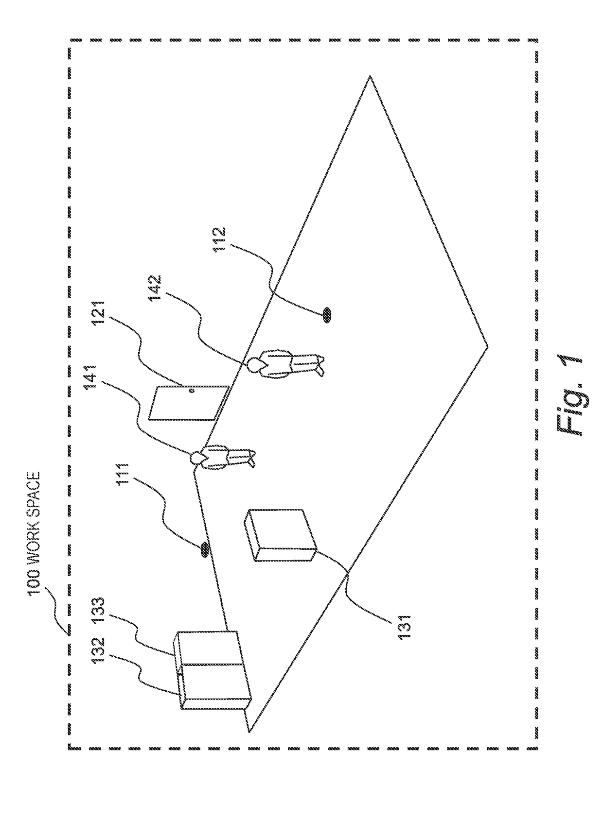
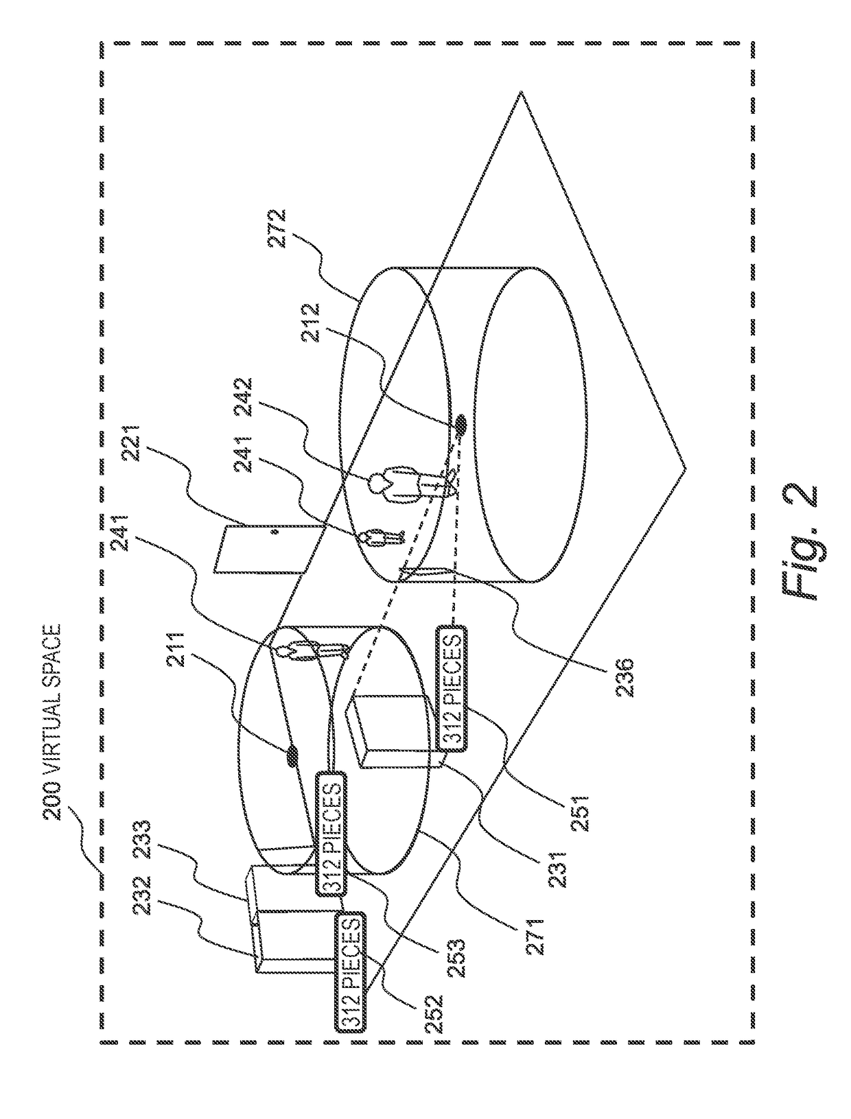
[0047]A system according to a first embodiment of this invention visualizes surroundings of a real space 100 illustrated in FIG. 1 on a virtual space 200 illustrated in FIG. 2. FIG. 1 is a diagram for illustrating the space 100 in which actual work is conducted.

[0048]The real space 100 is a real space to be represented. Cameras 111 and 112 capable of 360-degree photography described later are installed in the space 100. The cameras 111 and 112 are installed on a ceiling of a room serving as the work space 100. Instead, the cameras 111 and 112 may be installed on a floor, or at a predetermined height (e.g., 1 meter) from the floor.

[0049]Further, the space 100 includes a door 121. The door 121 may be a door for getting into or out of the room serving as the work space 100, or may be an elevator door.

[0050]Further, the space 100 accommodates equipments 131 to 133 fixedly installed in the space 100. As described later, the equipments 131 to 133 include electronic devices capable of elec...

second embodiment

[0121]In a second embodiment of this invention, a description is given of a calculation method for arranging the cylindrical virtual screen. In the second embodiment, only the configuration and processing different from those of the first embodiment are described, and a description of the same configuration and processing is omitted.

[0122]FIG. 14A and FIG. 14B are diagrams for illustrating arrangement of cameras for capturing the entire peripheral image and arrangement of the virtual screen.

[0123]As illustrated in FIG. 14A, when virtual screens are densely arranged (Step 1401), cylinders overlap with one another to result in display mode that is difficult to see. However, as illustrated in FIG. 14B, when a part of the cameras is set to a non-display mode, some virtual screens are removed and remaining virtual screens are arranged (Step 1402). In this manner, in the second embodiment, a description is given of a method of automatically calculating the radius of the cylindrical virtua...

third embodiment

[0137]In a third embodiment of this invention, user interaction using a three-dimensional maker arranged in the photographing position of the camera is described. In the system according to the third embodiment, it is possible to change the viewpoint position for rendering a three-dimensional model, modify the virtual screen on which an entire peripheral image is projected, and select an entire peripheral image. In the third embodiment, only the configuration and processing different from those of the embodiments described above are described, and a description of the same configuration and processing is omitted.

[0138]The hardware configuration in the third embodiment is the same as that of the first embodiment, which is illustrated in FIG. 1 and FIG. 3. A common pointing device, for example, a mouse, is used as the input device 308 for the image generation device 302. In general, the operating system provides a mouse with means for sensing operation such as a click and a drag for s...


PUM


Abstract

To arrange an entire peripheral image in the virtual three-dimensional space in an easy-to-grasp manner, it is provided an image generation device, which is configured to generate an image to be displayed on a display device, the image generation device comprising: a processor configured to execute a program; and a memory configured to store the program, wherein the processor is configured to: arrange a three-dimensional model of an object existing in a real space in a virtual three-dimensional space; arrange at least one tube-shaped virtual screen including a predetermined photographing position in the virtual three-dimensional space; execute arithmetic processing of mapping an entire peripheral image captured at the predetermined photographing position to the at least one tube-shaped virtual screen; and generate image data for displaying, in a panoramic view, the virtual three-dimensional space in which the three-dimensional model and the at least one tube-shaped virtual screen are arranged.

Description

BACKGROUND OF THE INVENTION[0001]This invention relates to an image generation device.[0002]WO 2008 / 147561 A2 and JP 2007-226580 A are known as the background art of this technical field.[0003]In WO 2008 / 147561 A2, there is disclosed a system, which may be used to view a panoramic image. The system includes a panorama viewer configured to receive at least a portion of a first panoramic image and provide a viewport for displaying the portion of the first panoramic image. The viewport includes a three-dimensional overlay that is rendered with the first panoramic image. In a case where the three-dimensional overlay is rendered with the first panoramic image, the panorama viewer changes the orientation of the three-dimensional overlay in a three-dimensional space so as to match a change in orientation of the first panoramic image within the viewport.[0004]Meanwhile, in JP 2007-226580 A, there is disclosed an image output device including: an image storage unit configured to store two or...

Claims


Application Information

Patent Timeline
Patent Type & Authority Applications(United States)
IPC IPC(8): G06T19/20G06T15/00
CPCG06T19/20G06T15/005G06T15/205G06T15/20G06T2219/2016G06T2219/2021G06T19/00
Inventor UTSUGI, KEIKOBAYASHI, MIHOARA, KOJI
Owner HITACHI INFORMATION & CONTROL SOLUTIONS LTD
Learn More