Display manipulation device

a display and manipulation technology, applied in the field of display manipulation devices, can solve the problems that the tactile stimulus providing device cannot provide the tactile stimulus to the high sensitivity portion of the finger, and it is difficult for the operator to feel the tactile stimulus, so as to ensure that the operator feels the tactile stimulus and reliably provide the manipulation feeling

Inactive Publication Date: 2018-07-26
DENSO CORP
View PDF2 Cites 11 Cited by
  • Summary
  • Abstract
  • Description
  • Claims
  • Application Information

AI Technical Summary

Benefits of technology

[0007]The present disclosure has been made in view of the above difficulties, and an object of the present disclosure is to provide a display manipulation device that is capable of ensuring that a manipulation feeling is provided to an operator who manipulates an image of an insubstantial manipulation target which is screenlessly displayed in midair.
[0009]According to the present disclosure, the display manipulation device can control the high sensitivity portion high in the sensitivity to the tactile stimulus in an operator's manipulation body to orient a direction which is more susceptible to the tactile stimulus caused by the tactile sense provider by guiding the high sensitivity portion to an image of a manipulation target displayed in midair. Therefore, even with the tactile stimulus provided in a non-contact manner, the certainty that the operator feels the tactile stimulus is increased. According to the above configuration, the display manipulation device can reliably provide the manipulation feeling to the operator who manipulates the image of the insubstantial manipulation target which is displayed in midair.

Problems solved by technology

However, the tactile sense providing device cannot constantly provide the tactile stimulus to the high sensitivity portion of the finger which manipulates the image from the viewpoint of a positional relationship between the operator and the image displayed in midair.
For that reason, there may be a situation where it is difficult for the operator to feel the tactile stimulus depending on a state of a manipulation body such as the finger which manipulates the image.

Method used


Image

  • Display manipulation device
  • Display manipulation device
  • Display manipulation device

Examples


first embodiment

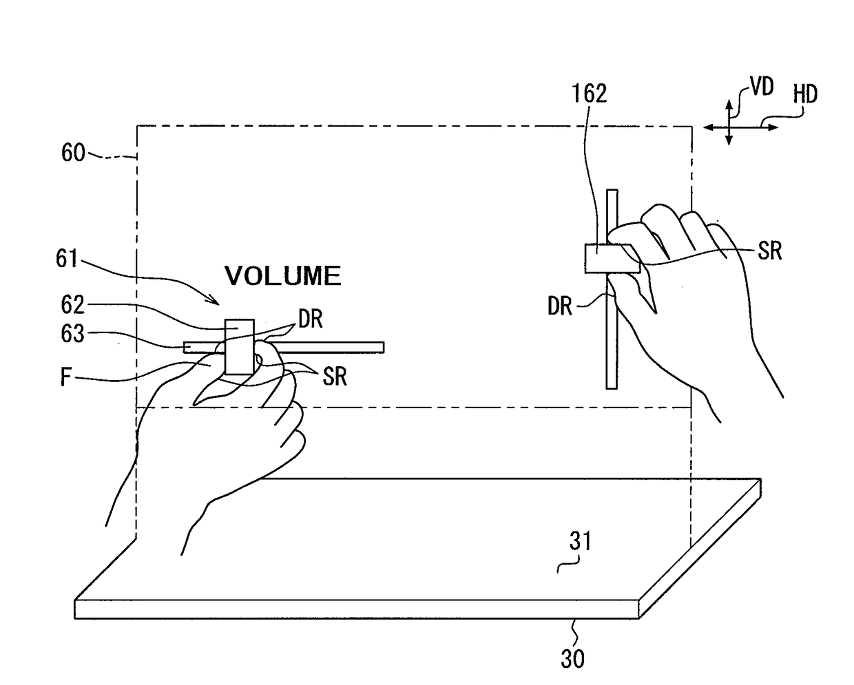
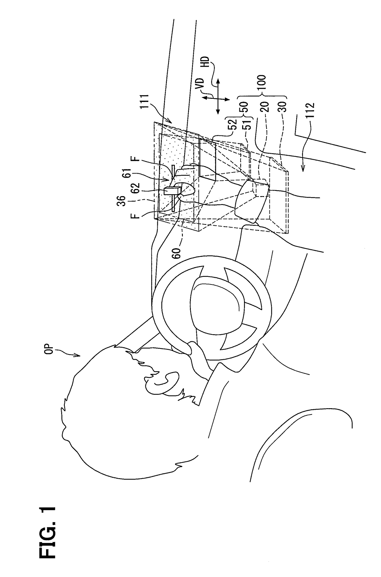
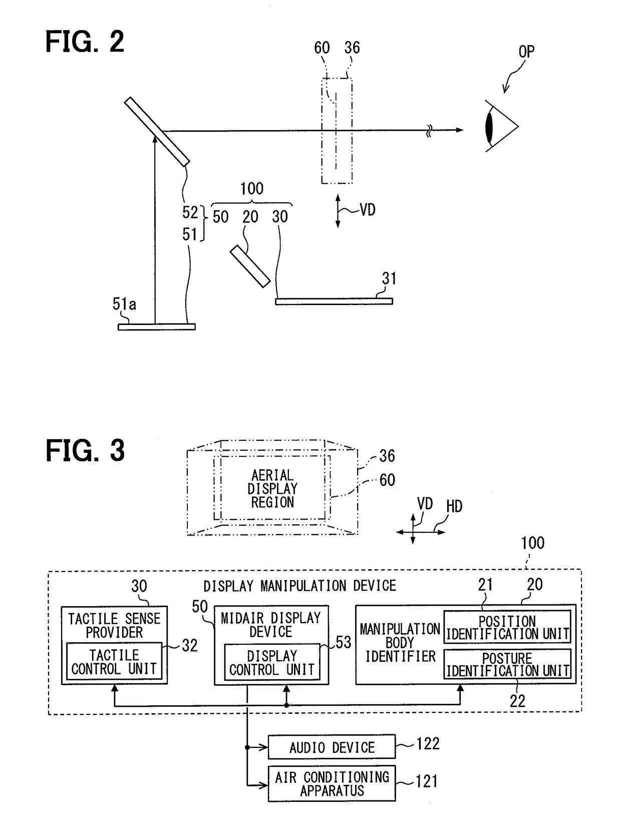
[0032]A display manipulation device 100 according to a first embodiment of the present disclosure shown in FIGS. 1 and 2 is installed in a vehicle and functions as a vehicle user interface that accepts the manipulation to operate other vehicle-mounted devices, such as an air conditioning apparatus 121 (refer to FIG. 3) and an audio device 122 (refer to FIG. 3). Each configuration of the display manipulation device 100 is accommodated in a center cluster 111 and a center console 112. The display manipulation device 100 displays an image of a manipulation target 61 on a virtual aerial display region 60 (refer to a dot area in FIG. 1) defined in a rectangular planar shape. The aerial display region 60 is defined in midair above the center console 112 and behind the center cluster 111. A driver sitting in a driver's seat, an occupant sitting in a front passenger seat, and so on can manipulate, as an operator OP an image of the virtual manipulation target 61 displayed in the midair betwe...

second embodiment

[0054]A second embodiment according to the present disclosure shown in FIG. 7 is a modification of the first embodiment. An image of a manipulation target 261 according to the second embodiment includes multiple push buttons 262. The multiple push buttons 262 are aligned in a horizontal direction HD along an ultrasonic generation portion 31. Each of the push buttons 262 is provided with a pressing surface 263 directed to an operator OP. The pressing surface 263 is slightly inclined upward toward a back side. Due to the inclination of the pressing surface 263, each push button 262 can be recognized by the operator OP as an input unit capable of being pushed downward where the tactile sense provider 30 is located.

[0055]When a push manipulation directed downward is entered by each push button 262, a display control unit 53 (refer to FIG. 3) displays an image in which the push button 262 that has entered the manipulation is pushed down. In addition, the tactile control unit 32 (refer to...

third embodiment

[0058]A third embodiment according to the present disclosure illustrated in FIGS. 8 and 9 is another modification of the first embodiment. A display manipulation device 300 according to the third embodiment includes a manipulation body identifier 20, a first tactile sense provider 330, a second tactile sense provider 340, a midair display device 350, and a control unit 310.

[0059]The first tactile sense provider 330 has a configuration similar to the tactile sense provider 30 according to the first embodiment. The tactile control unit 32 (refer to FIG. 3) included in the first tactile sense provider 330 is not shown. The first tactile sense provider 330 is disposed below an aerial display region 60 and can provide a tactile stimulus to a manipulation body such as a finger F that is present in a tactile sense providing region 36.

[0060]The second tactile sense provider 340 has substantially the same configuration as that of the first tactile sense provider 330, and is disposed on a bac...


PUM


Abstract

A display manipulation device, which enables an operator to manipulate an image of manipulation target displayed in midair, includes a midair display device, a position identifier, and a tactile sense provider. The midair display device displays the image of manipulation target in a virtual aerial display region defined in midair. The position identifier identifies a position of a manipulation body in the aerial display region. The tactile sense provider provides tactile stimulus to the manipulation body in a non-contact manner based on the identified position of the manipulation body when the manipulation body touches the image of manipulation target. The image of manipulation target is displayed to induce a state of the manipulation body so that a high sensitivity portion of the manipulation body, which is highly sensitive to the tactile stimulus, faces a direction susceptible to the tactile stimulus provided by the tactile sense provider.

Description

CROSS REFERENCE TO RELATED APPLICATION[0001]This application is based on Japanese Patent Application No. 2015-145926 filed on Jul. 23, 2015, the disclosure of which is incorporated herein by reference.TECHNICAL FIELD[0002]The present disclosure relates to a display manipulation device that enables an operator to manipulate an image of a manipulation target which is projected to be displayed in midair.BACKGROUND ART[0003]Up to now, for example, Patent Literature 1 discloses a tactile sense providing device that provides a stimulus caused by ultrasonic waves to a person skin, to thereby cause a person to feel a tactile stimulus as if touching an object. Such a tactile sense providing device is combined with a display device that displays a three-dimensional image by midair projection display technique, and an infrared camera that identifies a position of a finger or the like for manipulating the three-dimensional image. Such a combination forms an interaction system that is capable of...

Claims


Application Information

Patent Timeline
Patent Type & Authority Applications(United States)
IPC IPC(8): G06F3/01G06F3/0481G06F3/0484G06F3/0488
CPCG06F3/016G06F3/04815G06F3/04842G06F3/04847G06F3/0488G06F3/0425G06F3/04883G06F2203/04108
Inventor KITAGAWA, NOZOMI
Owner DENSO CORP
Why Eureka
Try Eureka