Plugged honeycomb structure

a honeycomb and structure technology, applied in the field of plugged honeycomb structure, can solve the problems of affecting the performance of the trapping, the influence of the engine output drop, and the influence of the fuel consumption, so as to reduce the pressure loss increase ratio, excellent trapping performance, and effective trapping performance

Active Publication Date: 2018-08-02
NGK INSULATORS LTD
View PDF0 Cites 11 Cited by
  • Summary
  • Abstract
  • Description
  • Claims
  • Application Information

AI Technical Summary

Benefits of technology

[0009]In purification of an exhaust gas by a plugged honeycomb structure, when the exhaust gas passes through pores formed in partition walls, PM in the exhaust gas is trapped in these pores. Therefore, it is considered that improvement of a trapping performance of the plugged honeycomb structure is achievable by decreasing large pores and increasing small pores in a pore distribution of the pores formed in the partition walls.
[0013]The present invention has been developed in view of such problems of a conventional technology. According to the present invention, there is provided a plugged honeycomb structure which has an excellent trapping performance and is capable of effectively inhibiting increase of pressure loss due to loading of an exhaust gas purifying catalyst and trapping of particulate matter. That is, there is provided a plugged honeycomb structure which is capable of suppressing to a lower level an increase ratio of pressure loss due to loading of an exhaust gas purifying catalyst and trapping of particulate matter, on the basis of the pressure loss of the plugged honeycomb structure prior to loading the exhaust gas purifying catalyst. Hereinafter, the above “increase ratio of the pressure loss due to loading of an exhaust gas purifying catalyst and trapping of particulate matter” will occasionally be referred to as “the pressure loss increase ratio”.
[0014]As a result of intensive studies to achieve a plugged honeycomb structure which has an excellent trapping performance and is capable of decreasing a pressure loss increase ratio, the present inventors have obtained the following findings. Initially, for the purpose of suppressing to a low level the pressure loss increase ratio after a catalyst is loaded and PM is trapped, it is effective to decrease a pore volume of pores having comparatively small pore diameters among pores formed in partition walls.
[0015]Hereinafter, “the pores having small pore diameters” will occasionally be referred to as “the small pores”. Furthermore, for improvement of the trapping performance, it is effective to decrease a pore volume of pores having comparatively large pore diameters among the pores formed in the partition walls. Hereinafter, “the pores having large pore diameters” will occasionally be referred to as “the large pores”. On the other hand, the pressure loss of the plugged honeycomb structure is also influenced by a porosity of the partition walls. Consequently, when the small pores and large pores are decreased as described above, it is also important to increase a pore volume of pores having medium pore diameters except the small pores and the large pores. Hereinafter, “the pores having medium pore diameters except the small pores and the large pores” will occasionally be referred to as “the medium pores”. Here, as to the medium pores whose pore volume increases, it is useful to decrease variations of a distribution including a maximum value of the pore volume in a medium pore diameter distribution, for the purpose of suppressing the pressure loss increase ratio to a low level. In other words, it is useful to sharpen a peak including the maximum value of the pore volume of the medium pores, for the purpose of suppressing the pressure loss increase ratio to a low level. In consequence, it has been found that when a pore diameter distribution of the partition walls is obtained so that all the above-mentioned conditions are established, the plugged honeycomb structure which has the excellent trapping performance and is capable of decreasing the pressure loss increase ratio is achievable.
[0032]The present invention produces the effect that a plugged honeycomb structure has an excellent trapping performance and is capable of decreasing a pressure loss increase ratio. Specifically, in the plugged honeycomb structure of the present invention, a ratio of a volume of pores having pore diameters of 10 μm or less to a total pore volume of the partition walls is 41% or less, and a ratio of a volume of pores having pore diameters in a range of 18 to 36 μm to the total pore volume is 10% or less. Furthermore, in a pore diameter distribution of the partition walls in which the abscissa indicates the pore diameter and the ordinate indicates a log differential pore volume, the pore diameter indicating a maximum value of the log differential pore volume is in a range of 10 to 16 μm, and a half-value width of a peak including the maximum value of the log differential pore volume is 5 μm or less. According to such a constitution, when an exhaust gas purifying catalyst is loaded onto the partition walls, the pores formed in the partition walls are hard to be closed with the loaded catalyst, and also when PM is trapped in the pores, the pores formed in the partition walls are hard to be closed. In consequence, such a pore diameter distribution as described above makes it possible to realize an effective trapping performance as a filter to trap the PM in an exhaust gas emitted from an internal combustion engine.

Problems solved by technology

Consequently, in a conventional plugged honeycomb structure, there has been the problem that the catalyst loaded onto the partition walls often enters and closes the pores having comparatively smaller pore diameters among the pores formed in the partition walls.
Consequently, in the conventional plugged honeycomb structure, there has been a problem that a pressure difference between an inflow end face side and an outflow end face side (pressure loss) increases, thereby causing fears of engine output drop and influence on fuel consumption.
For example, when the porosity increases, a volume of large pores increases, and there is the fear that the trapping performance is influenced.
In consequence, there has been a problem that when variations of the pore diameters increase, an increase ratio of pressure loss at the time of trapping PM after a catalyst is loaded noticeably rises.

Method used


Image

  • Plugged honeycomb structure
  • Plugged honeycomb structure
  • Plugged honeycomb structure

Examples


example 1

[0081]Silicon carbide (SiC) powder and metal silicon (Si) powder were mixed at a mass ratio of 80:20 to prepare a mixed raw material as raw material powder to prepare a kneaded material. An average particle diameter of the silicon carbide powder was 30 μm. An average particle diameter of the metal silicon powder was 4 μm. Additionally, in the present example, the average particle diameter of each raw material powder was measured by laser diffractometry.

[0082]6 parts by mass of a binder, 15 parts by mass of a pore former and 24 parts by mass of water were added to 100 parts by mass of the mixed raw material, to prepare a forming raw material for the preparation of the kneaded material. Methylcellulose was used as the binder. Starch having an average particle diameter of 15 μm was used as the pore former. Next, the obtained forming raw material was kneaded by using a kneader, to obtain the kneaded material.

[0083]Next, the obtained kneaded material was formed by using an extruder, to p...

examples 2 to 11

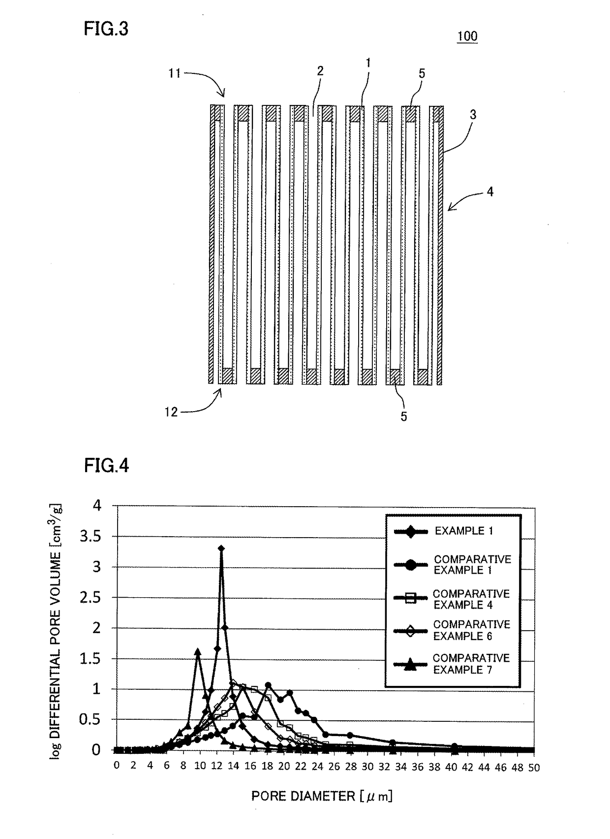
[0107]The procedure of Example 1 was repeated except that a thickness of partition walls, a porosity, an average pore diameter, a total pore volume and a pore volume ratio were changed as shown in Table 1, to prepare plugged honeycomb structures. The porosity, the average pore diameter and the like were adjusted by adjusting particle diameters and an amount of a pore former to be added to a forming raw material. For example, in Example 2, the forming raw material was prepared on the same conditions as in Example 1, except that the average particle diameter of the pore former was 15 μm and the amount of the pore former to be added was 20 parts by mass. Furthermore, as to Example 3 and others, the forming raw material was prepared by adjusting the amount of the pore former to be added (corresponding to “the amount of the pore former (mass %)” in Table 3) as shown in Table 2.

TABLE 3Total pore volumeAmount of pore former[cm3 / g][mass %]Example 10.29415Example 20.31820Example 30.30818Exam...


PUM

PropertyMeasurementUnit
porosityaaaaaaaaaa
thicknessaaaaaaaaaa
pore diametersaaaaaaaaaa

Abstract

A plugged honeycomb structure including: a pillar-shaped honeycomb structure body having porous partition walls made of a material including silicon carbide, and plugging portions, wherein a porosity of the partition walls is from 42 to 52%, a thickness of the partition walls is from 0.15 to 0.36 mm, a ratio of a volume of pores having pore diameters of 10 μm or less to a total pore volume of the partition walls is 41% or less, a ratio of a volume of pores having pore diameters in a range of 18 to 36 μm to the total pore volume is 10% or less, the pore diameter indicating a maximum value of the log differential pore volume is in a range of 10 to 16 μm, and a half-value width of a peak including the maximum value of the log differential pore volume is 5 μm or less.

Description

[0001]The present application is an application based on JP 2017-017465 filed on Feb. 2, 2017 with Japan Patent Office, the entire contents of which are incorporated herein by reference.BACKGROUND OF THE INVENTIONField of the Invention[0002]The present invention relates to a plugged honeycomb structure, and more particularly, it relates to a plugged honeycomb structure which has an excellent trapping performance and is capable of effectively decreasing an increase ratio of pressure loss due to loading of an exhaust gas purifying catalyst and trapping of particulate matter.Description of the Related Art[0003]Heretofore, plugged honeycomb structures in which honeycomb structures are used have been known as a filter to trap particulate matter in an exhaust gas emitted from an internal combustion engine such as a diesel engine, and a device to purify toxic gas components of CO, HC, NOx and the like (see Patent Documents 1 and 2). Such a honeycomb structure has partition walls made of po...

Claims


Application Information

Patent Timeline
Patent Type & Authority Applications(United States)
IPC IPC(8): B01D46/24B01J27/224B01J35/04B01J35/10C04B38/00B01D53/94
CPCB01D46/2429B01J27/224B01J35/04B01J35/1076B01J35/1038C04B38/0009B01D46/2474B01D46/247B01D53/94B01D2046/2433B01D2046/2437B01D2046/2481B01D2255/915B01D2279/30F01N3/0222F01N3/035F01N3/2828F01N2330/06F01N2330/02B01D46/24492B01D46/2482B01D46/24491B01D46/2476C04B2111/00793C04B2111/0081B01D53/9418B01D53/944B01D2255/1021B01D2255/1023B01D2255/1025B01D2255/2022B01D2255/2025B01D2255/2027B01D2255/2045B01D2255/20707B01D2255/20723B01D2255/20738B01D2255/20761B01D2255/50B01D2255/502B01D2255/91B01D2255/9155B01D2255/9205C04B35/565C04B38/0054C04B38/0074
Inventor ILDA, TOMOHIROMIURA, KAZUTOAOKI, TAKASHIYASUI, OSAMU
Owner NGK INSULATORS LTD
Why Eureka
Try Eureka