
Vehicle Spindle And A Method Of Attaching The Spindle to A Portion Of An Axle Housing

Active Publication Date: 2018-08-02
DANA HEAVY VEHICLE SYSTEMS GROUP LLC
View PDF0 Cites 7 Cited by
  • Summary
  • Abstract
  • Description
  • Claims
  • Application Information

AI Technical Summary

Benefits of technology

The patent describes a method for attaching a spindle to an axle half shaft housing. The spindle has bearing journals on its outer surface and a protruding portion. The spindle is aligned to a clocking angle and then attached to the housing using welds. The technical effect is a more precise attachment of the spindle to the axle half shaft housing, which improves the performance and reliability of the vehicle.

Problems solved by technology

While the friction welding process itself is relatively fast in comparison to other welding techniques, the friction welding process adds additional time and complexity to the overall assembly process for the drive axle assembly.
For instance, the friction welding process adds additional time and complexity to aligning the braking assembly to the desired clocking angle.
While there is additional equipment that can be purchased to aid in stopping the spindle at the desired clocking angle it adds additional time, complexity and expense to the overall assembly process for the drive axle assembly.
Additionally, a post welding straightening process is needed when the friction welding process results in a distortion in the drive axle geometry.

Method used


Image

  • Vehicle Spindle And A Method Of Attaching The Spindle to A Portion Of An Axle Housing
  • Vehicle Spindle And A Method Of Attaching The Spindle to A Portion Of An Axle Housing
  • Vehicle Spindle And A Method Of Attaching The Spindle to A Portion Of An Axle Housing

Examples


Embodiment Construction

[0019]It is to be understood that the invention may assume various alternative orientations and step sequences, except where expressly specified to the contrary. It is also understood that the specific devices and processes illustrated in the attached drawings, and described in the specification are simply exemplary embodiments of the inventive concepts disclosed and defined herein. Hence, specific dimensions, directions or other physical characteristics relating to the various embodiments of the invention disclosed are not to be considered as limiting, unless expressly stated otherwise.

[0020]It is within the scope of this disclosure, and as a non-limiting example, that the vehicle spindle disclosed herein may be used in automotive, off-road vehicle, all-terrain vehicle, construction, structural, marine, aerospace, locomotive, military, machinery, robotic and / or consumer product applications. Additionally, as a non-limiting example, the vehicle spindle disclosed herein may also be u...


PUM

PropertyMeasurementUnit
Angleaaaaaaaaaa
Diameteraaaaaaaaaa
Energyaaaaaaaaaa

Abstract

A vehicle spindle and a method of attaching the spindle to a portion of an axle half shaft housing. The spindle has an inner surface, an outer surface, one or more bearing journals on the outer surface of the spindle and a radially protruding portion circumferentially extending from at least a portion of the outer surface of an axially inboard end portion of the spindle. Prior to attaching the spindle to the axle half shaft housing, the one or more bearing journals are ground, a clocking angle for the radially protruding portion of the spindle is determined and the spindle is aligned to the determined clocking angle. Once the spindle is aligned to the determined clocking angle, the axially inboard end portion of the spindle is attached to an axially outboard end portion of the axle half shaft housing using one or more welds.

Description

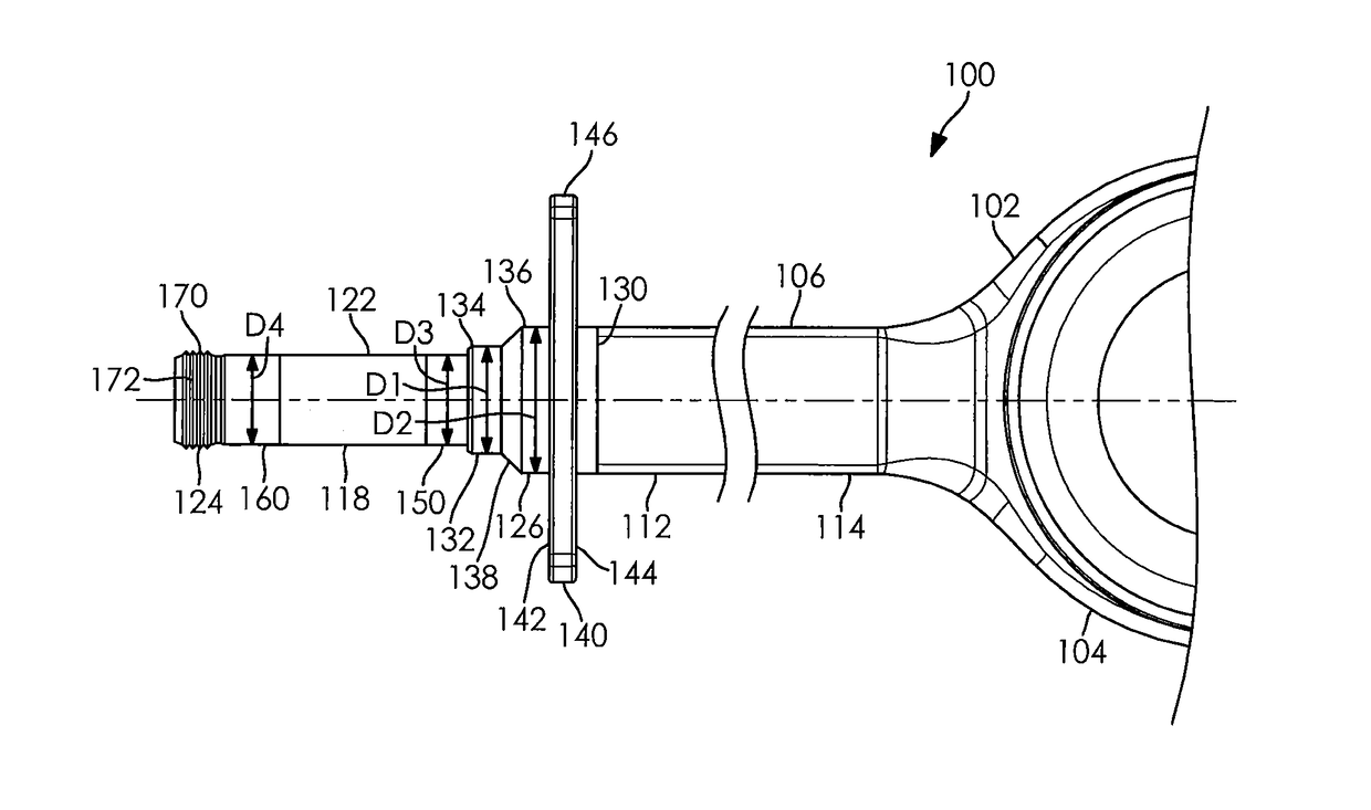
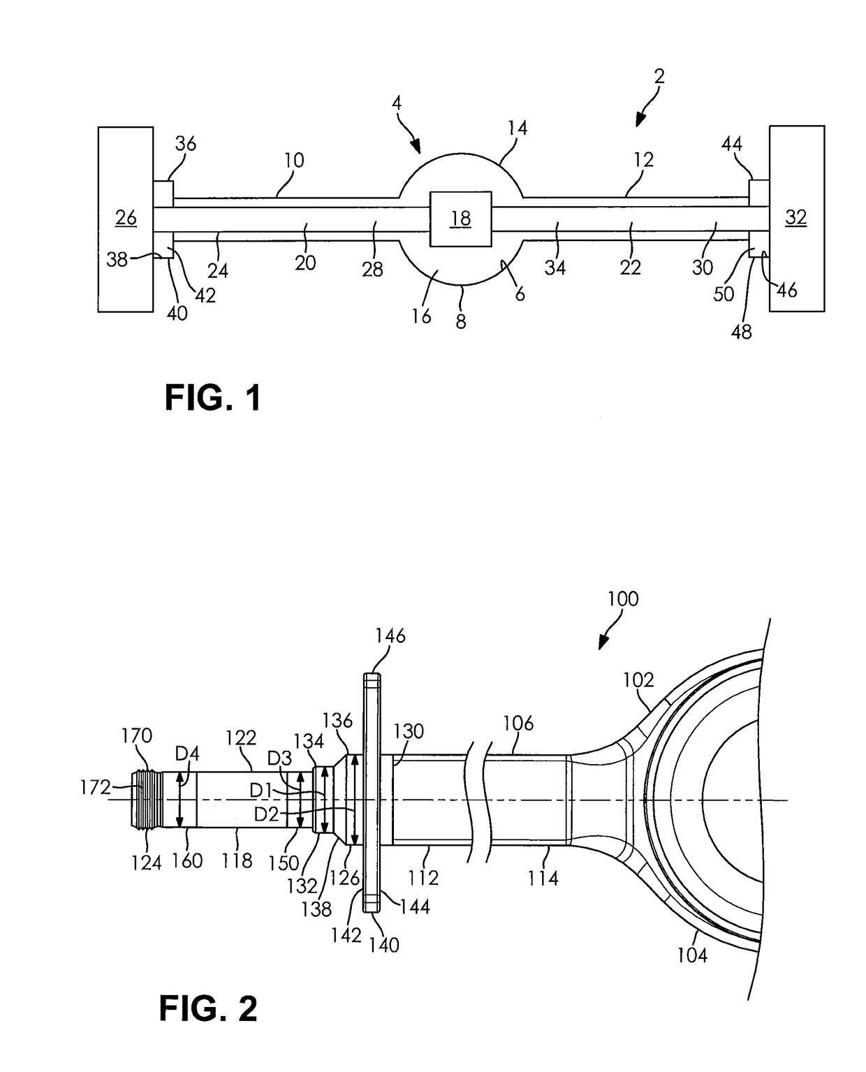
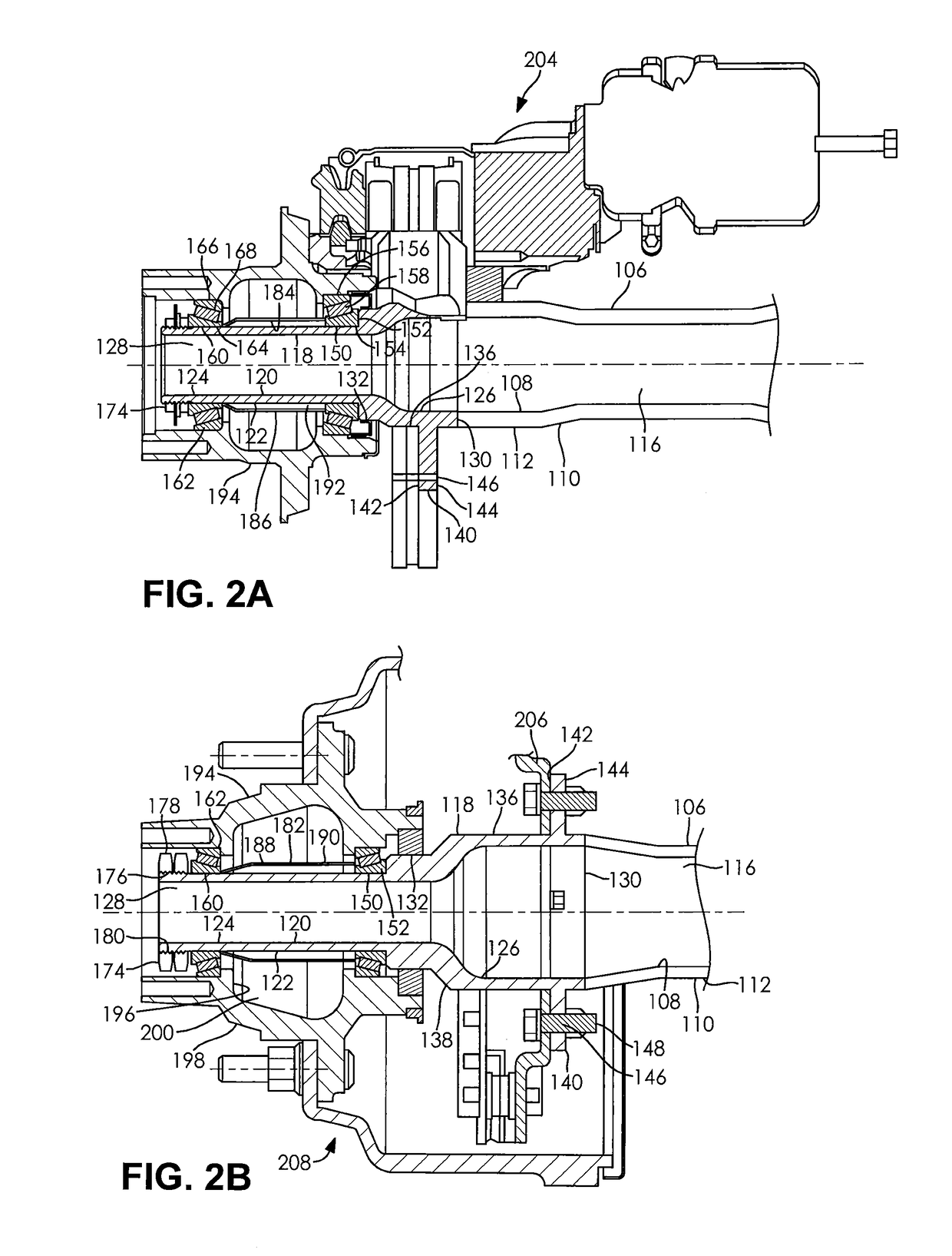
FIELD OF THE DISCLOSURE[0001]The present disclosure relates to a vehicle spindle and a method of attaching the spindle to a portion of an axle housing of a motor vehicle.BACKGROUND OF THE DISCLOSURE[0002]Conventional drive axle housings incorporate the use of a spindle as part of the suspension system that carries a wheel hub. The spindle is typically attached to an end of the drive axle housing using a friction welding process. During the friction welding process the spindle is spun at high speeds while in contact with the drive axle housing to generate an amount of mechanical friction between the two components. Once there is a sufficient amount of mechanical friction between the spindle and the drive axle housing, a lateral force is applied to plastically displace and fuse the two components together. While the friction welding process itself is relatively fast in comparison to other welding techniques, the friction welding process adds additional time and complexity to the overa...

Claims


Application Information

Patent Timeline
IPC IPC(8): B60B35/16B60B35/12B60B27/00B23K15/00B23K26/28
CPCB60B35/16B60B2900/113B60B27/0052B60B27/0057B23K15/0053B23K26/28B60B2900/112B60B2310/234B60B2310/302B60B2320/10B60B2310/3026B60B2310/3027B60B2310/54B60B2310/226F16D2250/0076F16D2051/003B60B27/06B60B2900/115B60B35/122F16C2326/06B23K31/02B60K17/36F16C35/063F16C35/067F16C3/02F16C19/548F16C33/581B60Y2410/10B23K2101/006B23K2101/06F16C19/364B60B27/0063B60B27/02F16C2326/02B60B35/00F16C35/12
Inventor TROST, HARRY W.SLESINSKI, STEVEN G.
Owner DANA HEAVY VEHICLE SYSTEMS GROUP LLC
Learn More