Valve

a technology for valves and diaphragms, applied in the field of valves, can solve the problems of limited material choice for diaphragms and limitation of valve applications

Active Publication Date: 2018-08-02
DANFOSS AS
View PDF7 Cites 2 Cited by
  • Summary
  • Abstract
  • Description
  • Claims
  • Application Information

AI Technical Summary

Benefits of technology

[0009]Furthermore, if a radial gap is arranged between the radially outer end of the diaphragm and the housing in a radial direction perpendicular to the opening direction of the pilot valve. This allows the diaphragm to expand in the radial direction, for example, due to an increase in temperature or an absorption of a refrigerant. This is in particular advantageous if the diaphragm is made from a material with a relatively large coefficient of thermal expansion.
[0022]It is preferred if a washer is arranged on the side of the diaphragm facing the inlet, wherein the washer limits the movement of a radial outer end of the diaphragm in an axial direction parallel to the opening direction of the pilot valve. The washer preferably has the shape of a ring disk with openings to allow the fluid flow from the inlet to the diaphragm or, in case the main valve is open from the inlet through the main valve opening towards the outlet. The washer can furthermore ensure that the radially outer end of the diaphragm does not get displaced out of the space between the housing and the washer, while still allowing the thermal expansion or contraction of the diaphragm, for example, into an axial gap or a radial gap. The diaphragm is preferably neither fixed to the housing nor the washer.

Problems solved by technology

Consequently, the choice of materials for the diaphragm is rather limited.
At the same time, the limited choice of materials also result in a limitation of the applications of the valve since the possible materials for the diaphragm are in some cases incompatible to certain fluids and / or pressure or temperature conditions.

Method used


Image

  • Valve
  • Valve
  • Valve

Examples


Embodiment Construction

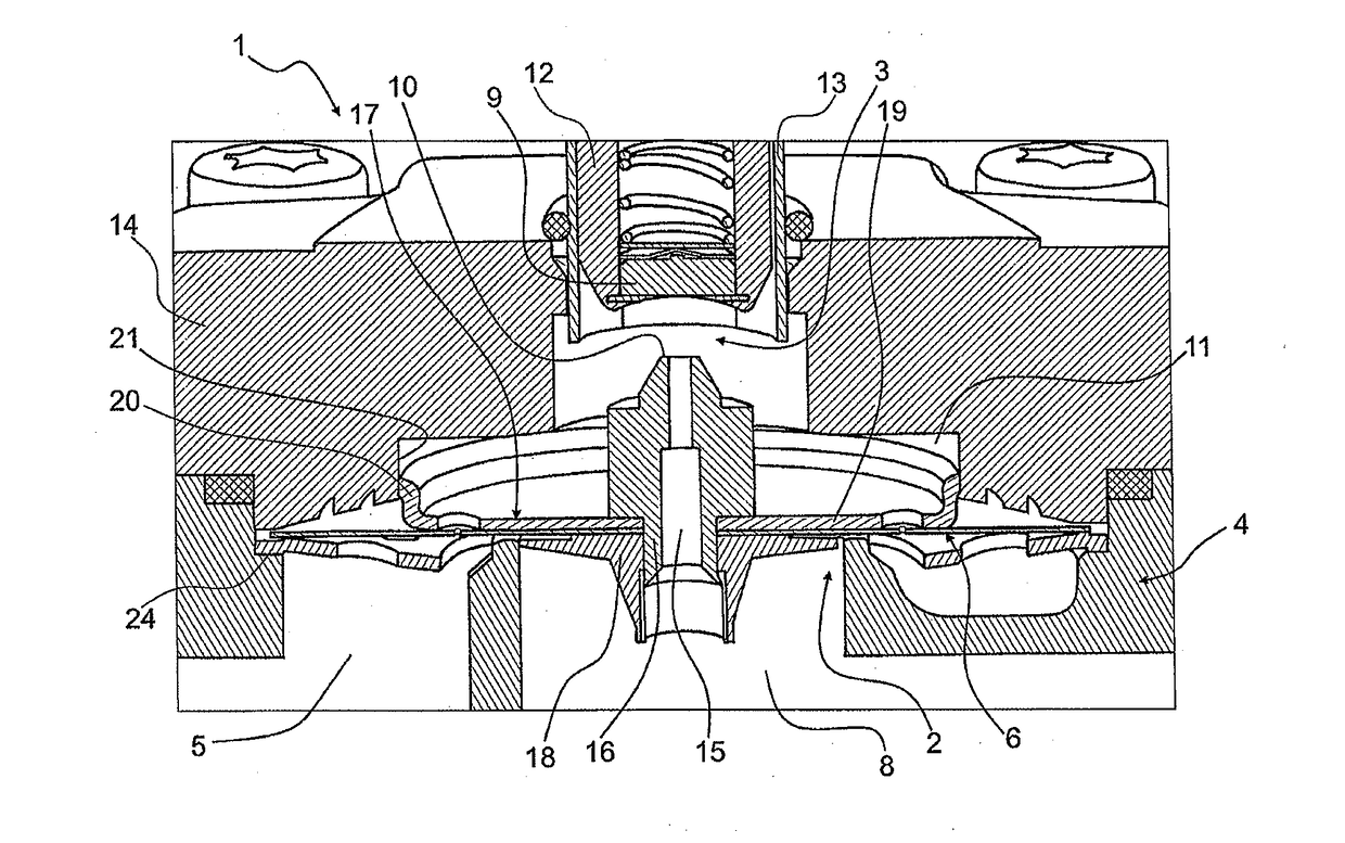
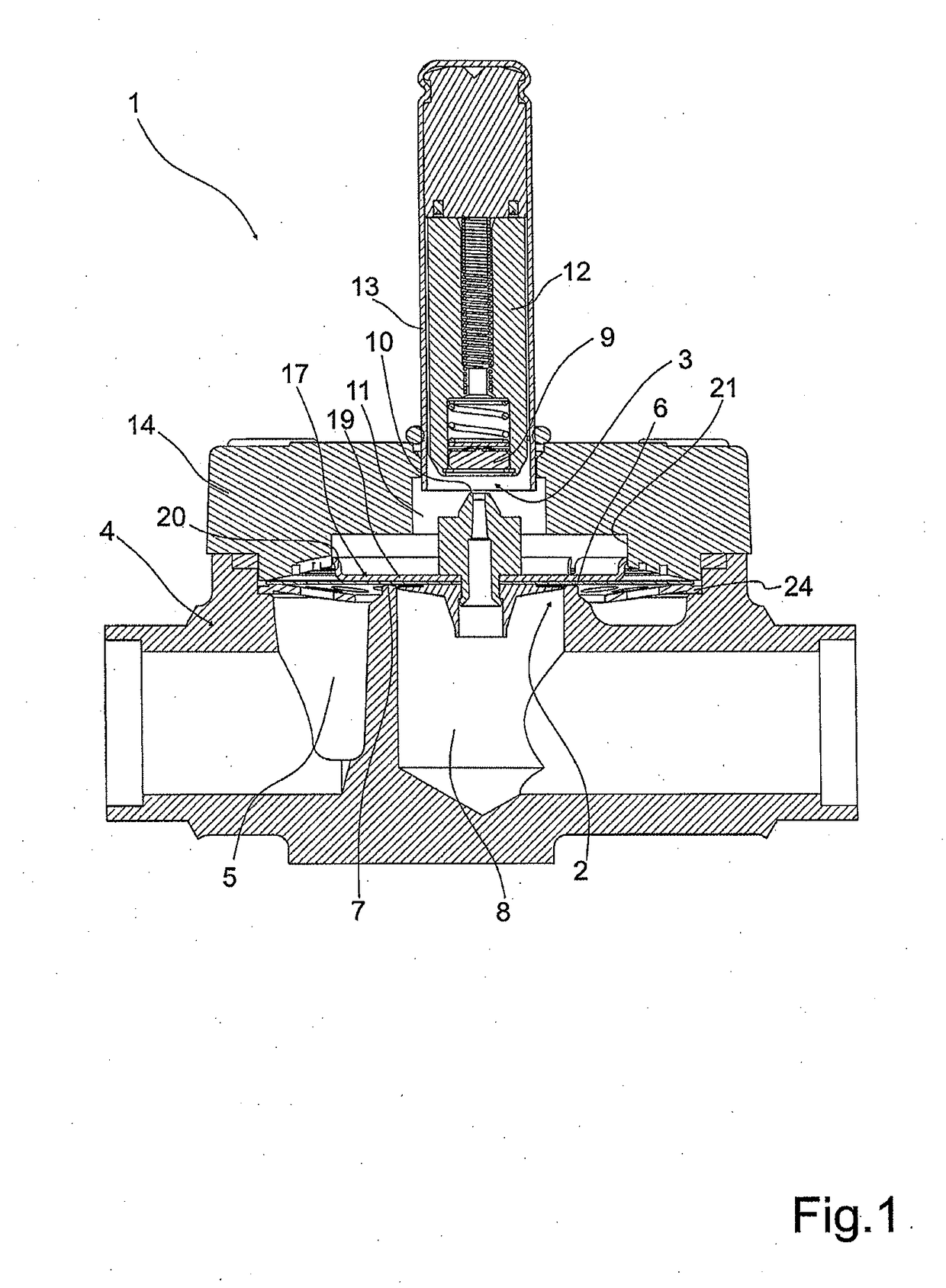
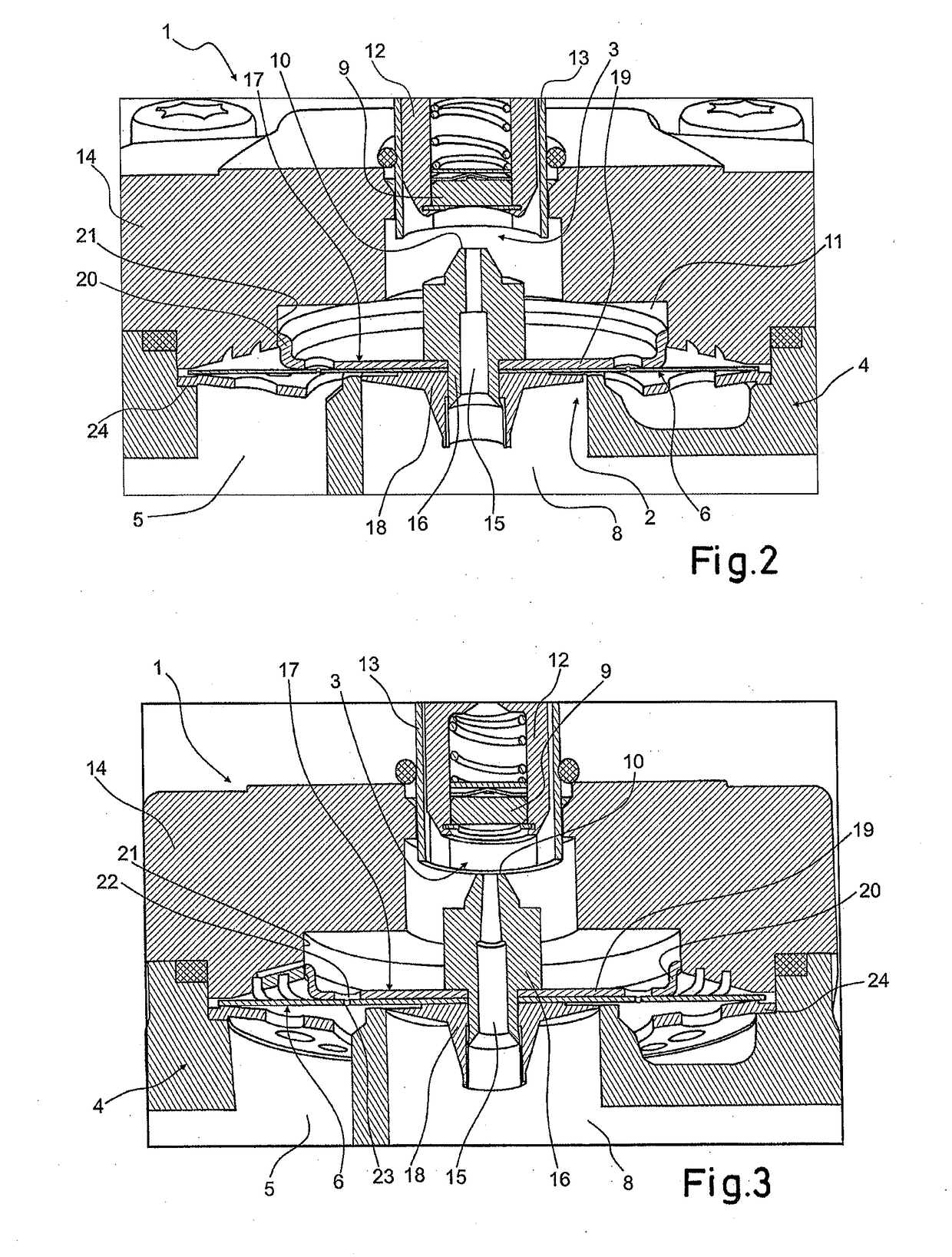
[0028]FIG. 1 to 5 show a valve 1 comprising a main valve 2 and a pilot valve 3. Both the main valve 2 and the pilot valve 3 are arranged in a common housing 4.

[0029]An inlet 5 leads to the main valve 2, which is in FIG. 1 to 5 closed by a diaphragm 6 engaging a main valve seat 7. In an open state of the main valve 2, the fluid can pass the main valve 2 towards an outlet 8.

[0030]The pilot valve 3 here is a solenoid valve, where the coil of the valve is not shown for simplicity. In FIG. 1 to 5 the pilot valve element 9 does not engage the pilot valve seat 10, and therefore the pilot valve 3 is open.

[0031]The diaphragm 6 separates the inlet 5 and the outlet 8 from a pilot chamber 11. The diaphragm 6 is preferably made from a non-reinforced polymer or rubber material.

[0032]The pilot valve 3 comprises a pilot valve member 12, in which the pilot valve element 9 is arranged.

[0033]The pilot valve member 12 is slidably arranged in an armature tube 13. The housing 4 comprises a cover 14 in wh...


PUM


Abstract

The invention relates to a valve (1) comprising a main valve (2), a pilot valve (3), a housing (4), an inlet (5) and an outlet (8). Opening and closing of the main valve (2) is controlled by the pilot valve (3). A pilot valve seat (10) is arranged in a diaphragm (6). A pilot chamber (11) is arranged in the housing (4) separated from the inlet (5) and the outlet (8) by the diaphragm (6). Task of the invention is to provide a valve with a lower cost. According to the invention a support member (17) supports the diaphragm (6), wherein the support member (17) is guided in the housing, and wherein a radial gap (26) is arranged between the radially outer end of the diaphragm (6) and the housing (4) in a radial direction perpendicular to the opening direction of the pilot valve (3). Thereby, a cheaper, less resistant material for the diaphragm can be used.

Description

CROSS-REFERENCE TO RELATED APPLICATION[0001]This application is a National Stage application of International Patent Application No. PCT / EP2016 / 067641, filed on Jul. 25, 2016, which claims priority to European Patent Application No. 15181333.4, filed on Aug. 18, 2015, each of which is hereby incorporated by reference in its entirety.TECHNICAL FIELD[0002]The invention relates to a valve comprising a main valve, a pilot valve, a housing, an inlet and an outlet, wherein opening and closing of the main valve is controlled by the pilot valve, and wherein a pilot valve seat is arranged in a diaphragm, and wherein a pilot chamber is arranged in the housing separated from the inlet and the outlet by the diaphragm.BACKGROUND ART[0003]Piloted valves are often used to control the flow of fluids, in particular under increased fluid pressure. The pilot valve is a directly controlled valve, e.g. a solenoid valve or the like. By operating the pilot valve the pressure differences between the pilot ...

Claims


Application Information

Patent Timeline
Patent Type & Authority Applications(United States)
IPC IPC(8): F16K31/40
CPCF16K31/404
Inventor PEDERSEN, ANDERSJENSEN, LEO FINN
Owner DANFOSS AS
Why Eureka
Try Eureka