Method for coating turbine blades

A technology for turbine blades and coatings, applied in the directions of blade support elements, coatings, metal material coating processes, etc., can solve the problems of TBC shedding, adhesion deterioration, etc., and achieve the effect of reducing the risk of local separation

Active Publication Date: 2019-12-27
SIEMENS ENERGY GLOBAL GMBH & CO KG
View PDF1 Cites 0 Cited by
  • Summary
  • Abstract
  • Description
  • Claims
  • Application Information

AI Technical Summary

Problems solved by technology

If this occurs where TBC should be coated, it makes its a

Method used


Image

  • Method for coating turbine blades
  • Method for coating turbine blades
  • Method for coating turbine blades

Examples


Embodiment Construction

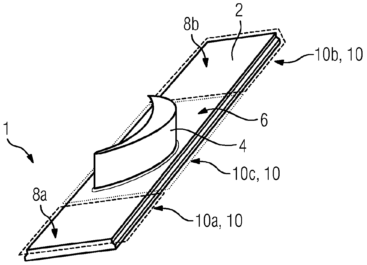
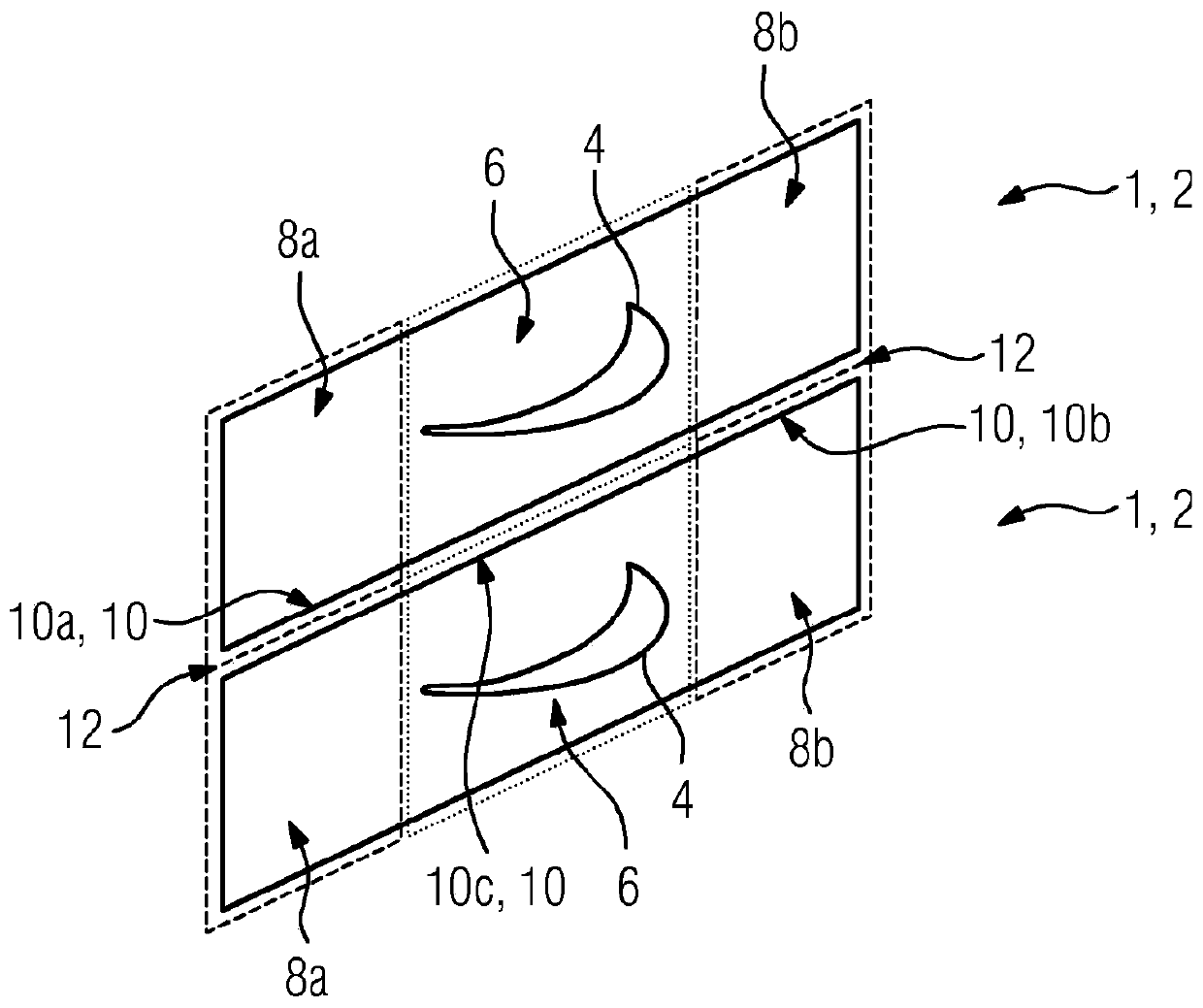
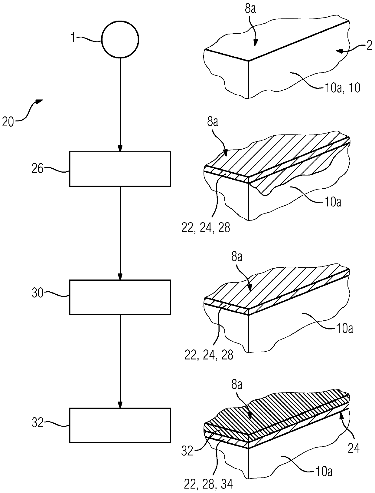
[0035] figure 1 An oblique view of the end of a turbine blade 1 is schematically shown in . Therein, the turbine blade 1 has a platform 2 and an airfoil 4 , wherein the airfoil 4 is implicitly indicated as the airfoil tip in the schematic illustration. The region of the platform 2 that is in contact with the airfoil 4 or transitions into the airfoil 4 is defined here as a contact region 6 . This is indicated by a dotted border. At the contact area 6, on the platform 2, in both directions, the airfoil 4 adjoins a convex protruding area 8a, 8b, respectively. These raised areas 8 a , 8 b are each marked here by a dashed border. If the first layer of the coating is now applied by spraying on the turbine blade 1 , it is generally unavoidable when spraying the platform 2 on the airfoil side that also wets the end face 10 of the platform 2 with a portion of the coating. In the region of the raised areas 8a, 8b, the remnants of the first layer of the coating are removed from the e...


PUM


Abstract

The invention proposes a method (2) for coating a turbine blade (1) comprising an airfoil (4) and at least one platform arranged at the end of the airfoil (4) (2), wherein the or each platform (2) has a contact region (6) and at least one planar raised region (8a, 8b) adjacent to the contact region (6), and the airfoil ( 4) terminating in the contact zone (6), with the following method steps: applying at least a first layer (22) of the coating (24) on the airfoil side on the platform (2), and applying the coating (24) ) of the at least first layer (22) remaining on the end face (10c) within the range of the contact zone (6), the at least first layer (22) of the coating (24) in the protruding zone (8a, 8b) are removed from at least one end face (10a, 10b) of the platform (2).

Description

technical field [0001] The invention relates to a method for coating a turbine blade comprising an airfoil and at least one platform arranged at the end of the airfoil, wherein the or each platform has a contact zone and at least one contact zone adjoins the raised area and terminates the airfoil at this contact area. Background technique [0002] Gradual switching of energy production to increasingly renewable energy carriers poses many technical challenges. Due to the very variable availability of, inter alia, wind energy and solar energy, which represent the two most important renewable energy carriers in many places, there is a need to equalize fluctuations in input power for stable network operation with constant supply power . In this context, gas turbines play a key role due to their high flexibility compared to other conventional energy carriers. [0003] Particularly in the case of power compensation for networks with strongly fluctuating loads, in which load cha...

Claims


Application Information

Patent Timeline
IPC IPC(8): C23C2/26C23C4/18C23C4/01C23C4/073F01D9/04
CPCC23C4/18F01D9/041F01D5/288F05D2240/80F05D2230/90C23C4/01C23C4/073C23C2/26
Inventor F·阿马德C·门克
Owner SIEMENS ENERGY GLOBAL GMBH & CO KG
Why Eureka
Try Eureka