Part processing and cleaning apparatus and method of same

a technology of cleaning apparatus and cleaning surface, which is applied in the direction of chemistry apparatus and processes, cleaning using liquids, manufacturing tools, etc., can solve the problems that the traditional cleaning form and process may not remove all particles or materials from the surface of the workpiece, and achieve the effect of roughening the gear surface and reducing the amount of dus

Active Publication Date: 2018-08-09
ENGINEERED ABRASIVES
View PDF0 Cites 2 Cited by
  • Summary
  • Abstract
  • Description
  • Claims
  • Application Information

AI Technical Summary

Benefits of technology

[0009]An object of the present invention is to remove or reduce particulates or particles on the surface of a workpiece that has been subjected to a peening process. In illustrative embodiments, the workpiece is subjected to a multi-step cleaning process after it has been processed / peened. The peening step(s) toughen the gears and provide roughness to the gear surfaces. The multi-step cleaning process after peening removes or reduces the particles or particulates that remain on the surface of the workpiece after processing.

Problems solved by technology

However, given the microscopic size of the particles, the force at which the peening material is blasted, and the shape and size of the workpieces being processed, traditional forms and processes of cleaning may not remove all particles or material from the surface of the workpiece.

Method used


Image

  • Part processing and cleaning apparatus and method of same
  • Part processing and cleaning apparatus and method of same
  • Part processing and cleaning apparatus and method of same

Examples


Embodiment Construction

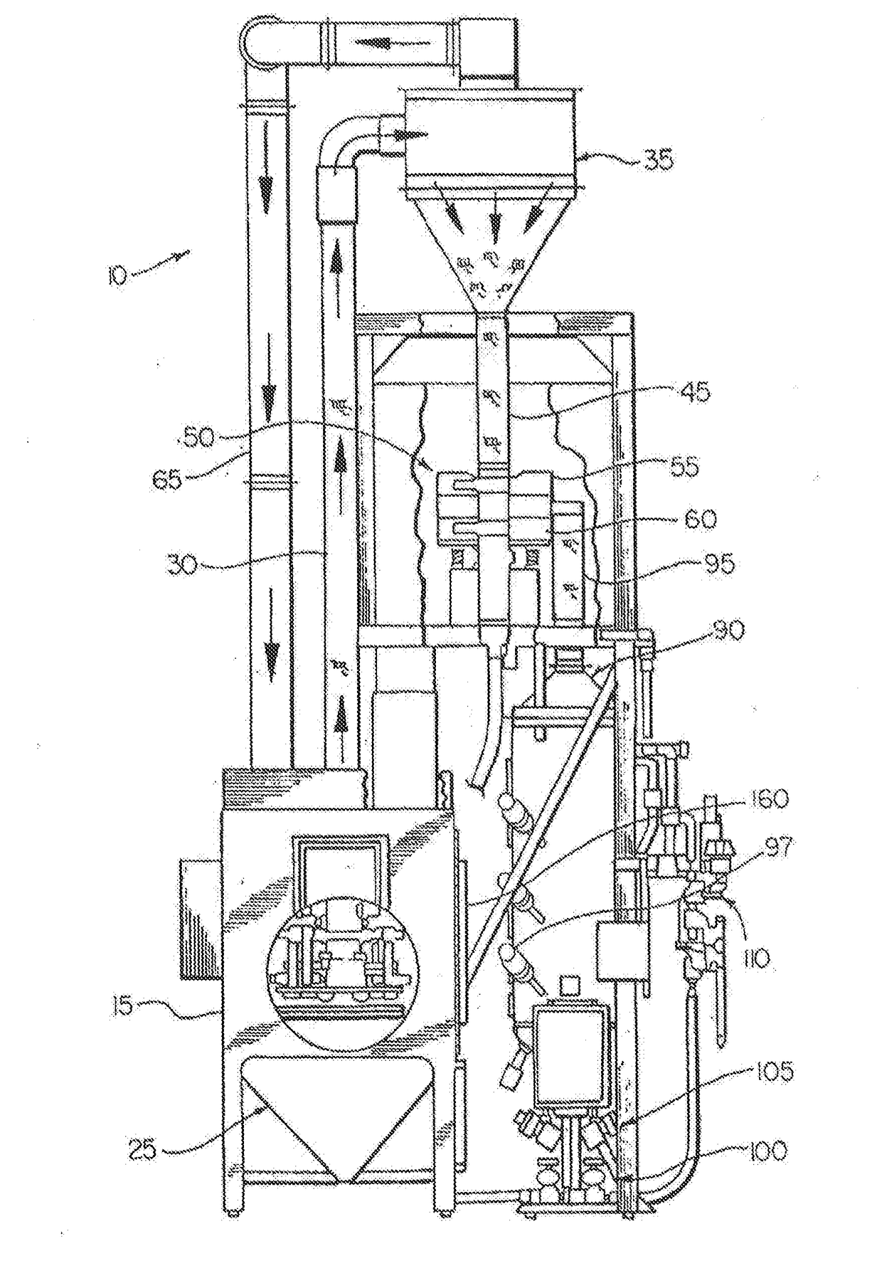
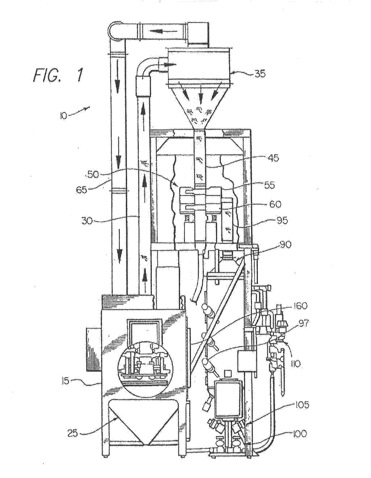
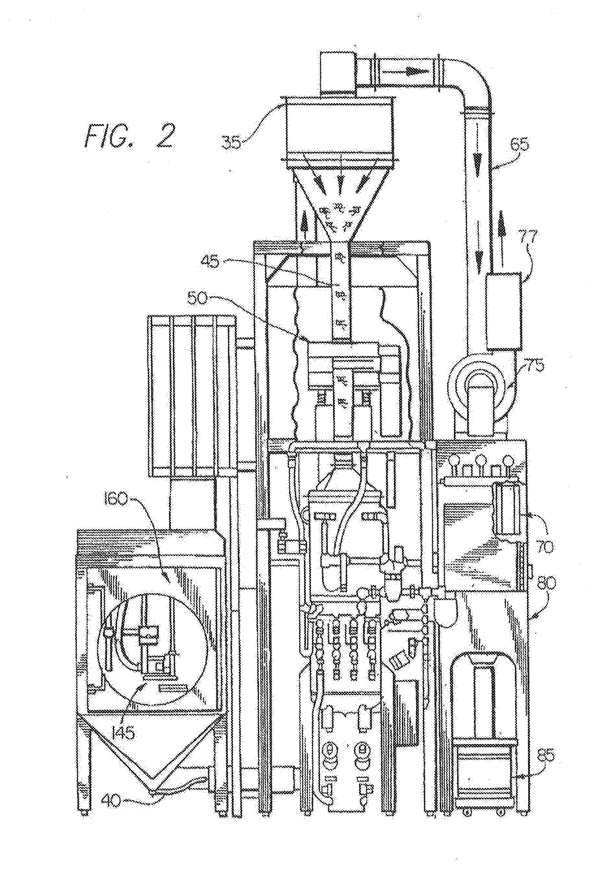
[0021]Referring now to the drawings, FIGS. 1-4 illustrate a media blasting apparatus according to the invention, generally indicated by the number 10. FIG. 5 illustrates a flow diagram for a part processing-and-cleaning process accordingly to the invention. FIG. 6 illustrates an exemplary flow layout of a media blasting apparatus and a cleaning apparatus of the present disclosure. FIGS. 7 and 8 illustrate components of the cleaning apparatus of the present disclosure.

[0022]The media blasting apparatus 10 will now be described. As illustrated in FIGS. 1-4, the media blasting apparatus 10 includes a blasting cabinet or chamber 15, in which a stream of media is directed against a workpiece 20. Such media may comprise, for example, cut wire, glass beads, ceramic beads or fine steel beads. As the media engages with the surface of the workpiece, microscopic or small particles from the media may be retained or lodged into the surface of the workpiece due to the force and direction of the b...


PUM

PropertyMeasurementUnit
toughnessaaaaaaaaaa
pressureaaaaaaaaaa
pressureaaaaaaaaaa

Abstract

A part processing apparatus and method is disclosed that includes a media-blasting apparatus and a cleaning apparatus. The media-blasting apparatus is configured to blast a stream of media against a surface of a part, and the cleaning apparatus is configured to clean debris or particles from the surface of the part. The cleaning apparatus includes a first spray-and-wash unit, a first ultrasonic wash unit, a second ultrasonic wash unit, and a second spray-and-wash unit. The first ultrasonic wash unit is configured to ultrasonically vibrate a liquid in the first ultrasonic wash unit at a first frequency, and the second ultrasonic wash unit is configured to ultrasonically vibrate a liquid in the second ultrasonic wash unit at a second frequency. The first and second frequencies may be different from each other, such that vibration at the second frequency causes additional debris or particles to be removed from the surface of the part.

Description

CROSS REFERENCE TO RELATED APPLICATIONS[0001]This application is a Continuation of co-pending U.S. patent application Ser. No. 15 / 337,133, filed Oct. 28, 2016, which claims the benefit of priority under 35 U.S.C. § 119(e) to U.S. Provisional Patent Application No. 62 / 254,051, filed Nov. 11, 2015. The disclosure set forth in the referenced application is incorporated herein by reference in its entirety.BACKGROUND OF THE INVENTION[0002]This invention relates generally to a method for media blasting and finishing a gear or other workpiece or part and cleaning the workpiece thereafter. The powered part hold-down apparatus of U.S. Pat. No. 5,272,897 may be used for the peening step(s) of the present disclosure, and the disclosure of the U.S. Pat. No. 5,272,897 is hereby incorporated in its entirety by this reference. Elements of other known methods of media blasting and finishing, such as the peen finishing method and apparatus of U.S. Pat. No. 8,453,305, may be used for the present disc...

Claims


Application Information

Patent Timeline
Patent Type & Authority Applications(United States)
IPC IPC(8): B24C1/10B24C9/00B24C3/26
CPCB24C9/00B24C1/10B24C3/26B08B3/12B08B3/123
Inventor WERN, MICHAEL J.
Owner ENGINEERED ABRASIVES
Why Eureka
Try Eureka