
Methods for Manufacturing Spar Caps for Wind Turbine Rotor Blades

a technology for wind turbines and rotor blades, applied in the field of wind turbines, can solve problems such as difficulty in transporting spar caps to the molds

Active Publication Date: 2018-08-09
GENERAL ELECTRIC CO
View PDF5 Cites 7 Cited by
  • Summary
  • Abstract
  • Description
  • Claims
  • Application Information

AI Technical Summary

Benefits of technology

The present patent is directed to a method for manufacturing a spar cap of a wind turbine rotor blade. The method involves forming an outer frame of the spar cap using 3D pultrusion, thermoforming, or 3D printing, and then arranging a plurality of structural materials within the outer frame. The structural materials may include thermoplastic or thermoset plies or pultruded members. The method also includes infusing the structural materials and the outer frame with a resin material to form the spar cap and allowing it to cure. The spar cap has a varying cross-section that matches the cross-section of the rotor blade along its span. The method may also include machining the structural materials, adding a non-structural layer, or adding a reinforcing material to the outer frame. The spar cap is designed to provide flexibility and strength to the wind turbine rotor blade.

Problems solved by technology

Once the pultruded plates are machined, however, transportation to the spar cap mold can be difficult.

Method used


Image

  • Methods for Manufacturing Spar Caps for Wind Turbine Rotor Blades
  • Methods for Manufacturing Spar Caps for Wind Turbine Rotor Blades
  • Methods for Manufacturing Spar Caps for Wind Turbine Rotor Blades

Examples


Embodiment Construction

[0049]Reference now will be made in detail to embodiments of the invention, one or more examples of which are illustrated in the drawings. Each example is provided by way of explanation of the invention, not limitation of the invention. In fact, it will be apparent to those skilled in the art that various modifications and variations can be made in the present invention without departing from the scope or spirit of the invention. For instance, features illustrated or described as part of one embodiment can be used with another embodiment to yield a still further embodiment. Thus, it is intended that the present invention include such modifications and variations as come within the scope of the appended claims and their equivalents.

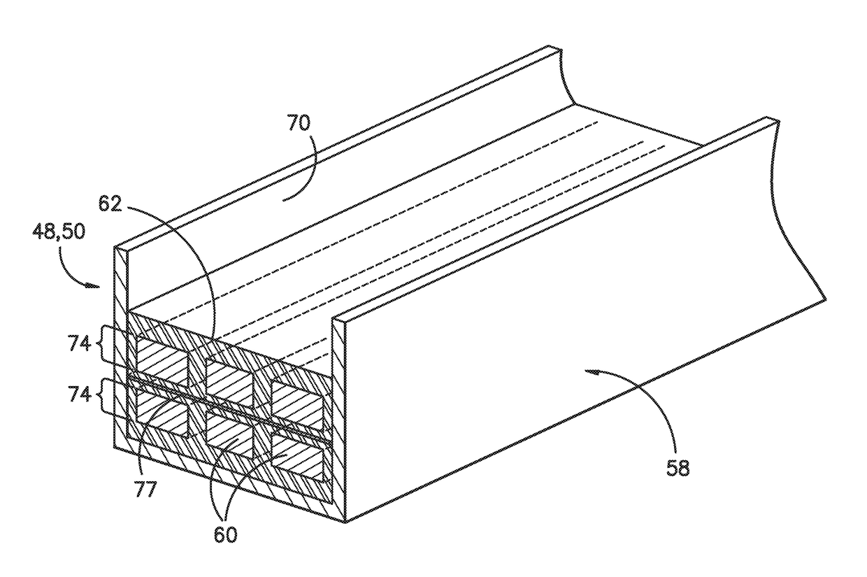
[0050]Generally, the present disclosure is directed methods for manufacturing spar caps for wind turbine rotor blades. More specifically, in certain embodiments, the method includes forming an outer frame of the spar cap via at least one of 3D pultrusion, ...


PUM

PropertyMeasurementUnit
Pressureaaaaaaaaaa
Flexibilityaaaaaaaaaa
Shapeaaaaaaaaaa

Abstract

The present disclosure is directed methods for manufacturing spar caps for wind turbine rotor blades. In certain embodiments, the method includes forming an outer frame of the spar cap via at least one of three-dimensional (3D) pultrusion, thermoforming, or 3D printing. As such, the outer frame has a varying cross-section that corresponds to a varying cross-section of the rotor blade along a span thereof. The method also includes arranging a plurality of structural materials (e.g. layers of pultruded plates) within the pultruded outer frame of the spar cap and infusing the structural materials and the outer frame together via a resin material so as to form the spar cap. The resulting spar cap can then be easily incorporated into conventional rotor blade manufacturing processes and / or welded or bonded to an existing rotor blade.

Description

FIELD OF THE INVENTION[0001]The present invention relates generally to the field of wind turbines, and more particularly to methods for manufacturing spar caps for wind turbine rotor blades.BACKGROUND OF THE INVENTION[0002]Wind power is considered one of the cleanest, most environmentally friendly energy sources presently available, and wind turbines have gained increased attention in this regard. A modern wind turbine typically includes a tower, a generator, a gearbox, a nacelle, and one or more rotor blades. The rotor blades are the primary elements for converting wind energy into electrical energy. The blades have the cross-sectional profile of an airfoil such that, during operation, air flows over the blade producing a pressure difference between the sides. Consequently, a lift force, which is directed from a pressure side surface towards a suction side surface, acts on the blade. The lift force generates torque on the main rotor shaft, which is geared to the generator for produ...

Claims


Application Information

Patent Timeline
IPC IPC(8): F03D1/06B29C70/52B29C51/26B29C67/00B33Y10/00B33Y80/00
CPCF03D1/0675B29C70/52B29C51/266B29C67/0055B33Y10/00B29L2031/085F05B2230/24F05B2280/6003B29K2105/06B29K2995/0082B33Y80/00B29C33/0016B29C51/10B29C51/12B29D99/0028B29C64/106Y02E10/72Y02P70/50
Inventor CARUSO, CHRISTOPHER DANIELYARBROUGH, AARON A.HYNUM, DANIEL ALANTOBIN, JAMES ROBERT
Owner GENERAL ELECTRIC CO
Learn More