Method and Device for Producing a Metal Component

a technology of metal structural components and metal components, applied in metal layered products, metal-working apparatuses, vehicle components, etc., can solve the problems of failure of the material following a relatively low energy absorption, and the failure of the material at the fracture of the hot-formed metal structural component is relatively low

Inactive Publication Date: 2012-07-26
THYSSENKRUPP STEEL EURO AG
View PDF2 Cites 42 Cited by
  • Summary
  • Abstract
  • Description
  • Claims
  • Application Information

AI Technical Summary

Benefits of technology

[0009]If the thermal conductivity of the adjacent surface is high, a rapid cooling of the steel part occurs, whereas if the thermal conductivity is low the steel part cools more slowly. On account of the adjustment of the cooling rate through the thermal conductivity of the tool surface the number of tempering elements, i.e. the heating or cooling elements, can be reduced, resulting in a cost saving. In addition, a non-uniform arrangement or a necessary controllability of the tempering elements can be dispensed with. This results in a cost reduction, too.
[0038]In a preferred embodiment at least one region of the batch furnace has controllable gas nozzles for cooling purposes. In this way, the regions with the different temperatures can be realised in a flexible and simple manner.

Problems solved by technology

The disadvantage of completely hot-formed metal structural components is that the elongation at fracture of a hot-formed metal structural component is relatively low.
Hot-formed metal structural components cannot, however, be used in the case of longitudinally stressed metal structural components, such as for example longitudinal members, since the low elongation at fracture would not allow a uniform folding of the metal structural components and the consequence would be a failure of the material following a relatively low energy absorption.
This method has the disadvantage that only two to three different zones as regards strength and elongation at fracture can be achieved in the metal structural component.
The forming tools with the means for tempering are however relatively complicated to produce and are therefore expensive.

Method used


Image

  • Method and Device for Producing a Metal Component
  • Method and Device for Producing a Metal Component
  • Method and Device for Producing a Metal Component

Examples


Embodiment Construction

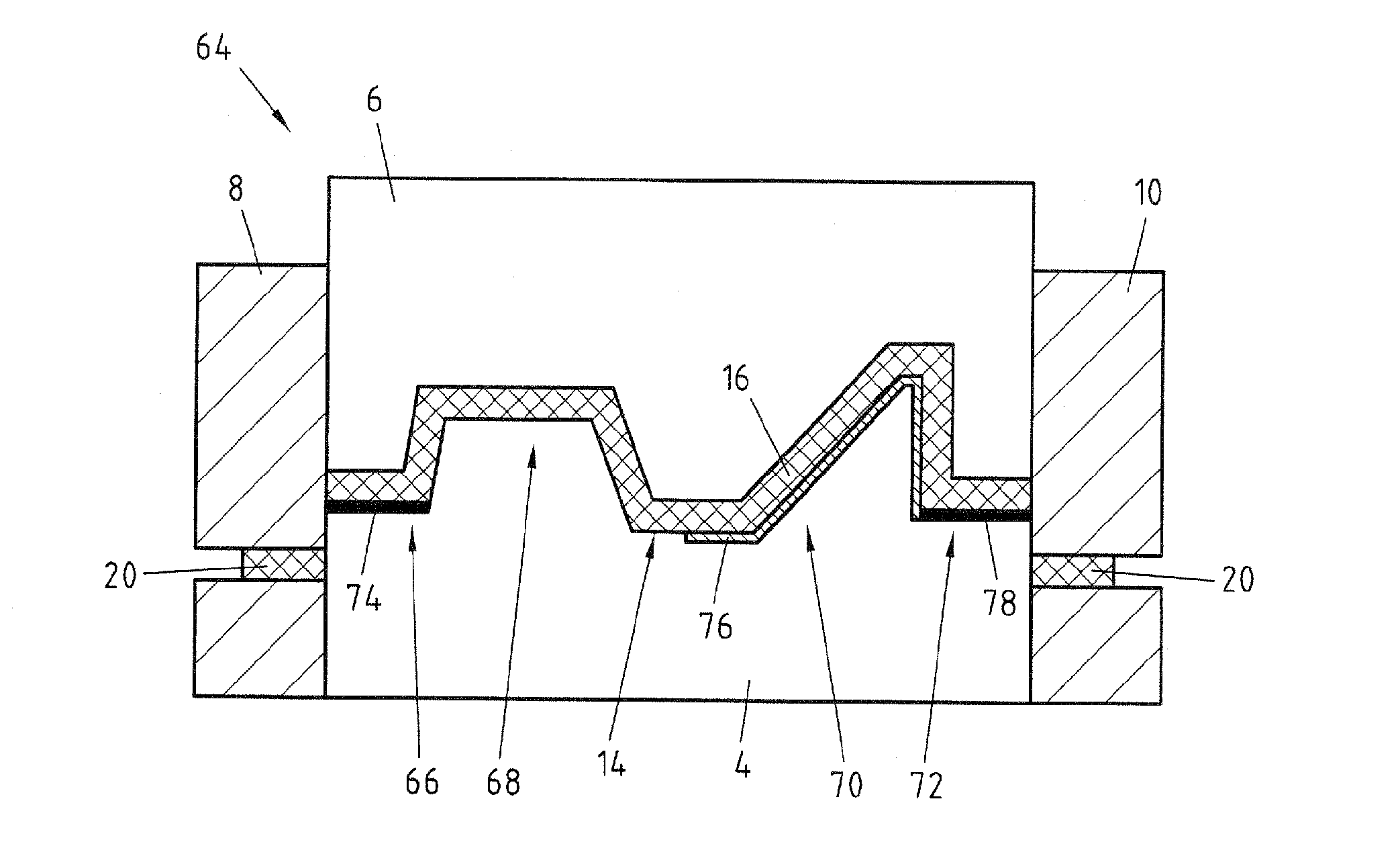
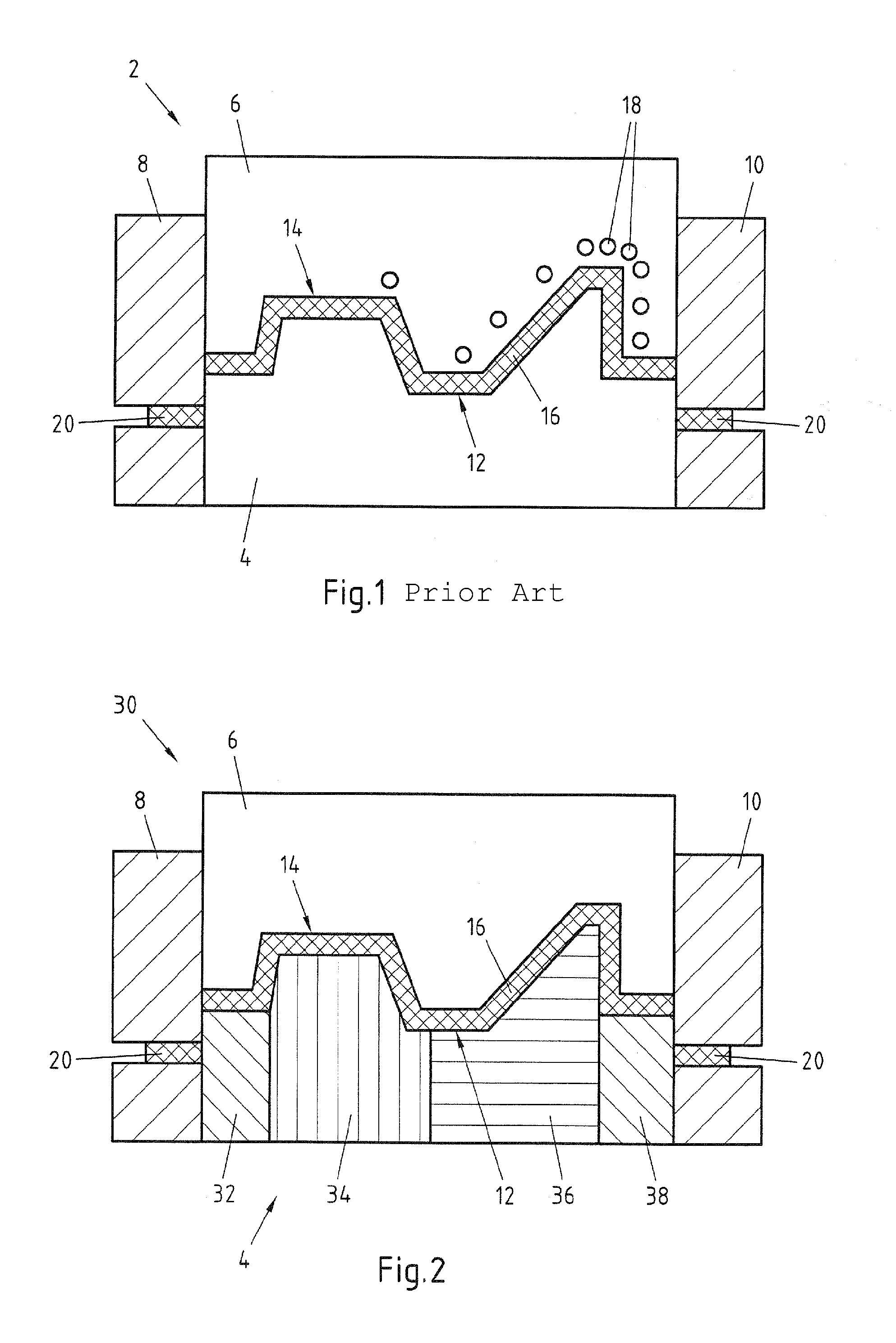
[0050]FIG. 1 shows a longitudinal section of a tool for producing a metal structural component from the prior art. The tool 2 is designed as a hot forming tool and has a lower punch 4, an upper punch 6 as well as two flange cutters 8 and 10. The surfaces 12 and 14 facing one another of the lower and upper punch 4, 6 have a profile that corresponds to the external contour of the metal structural component to be produced from a steel part 16. Tempering elements 18 are, furthermore, provided in the upper punch 6, with which the temperature in the region of the surface 14 of the upper punch 6 can be adjusted. Similar tempering elements can also be provided in the lower punch 4. The distances between the adjacent tempering elements 18 differ from one another, so that the surface 14 has a location-dependent temperature profile. In the production method of the prior art the steel part 16 in the form of a sheet bar is arranged between the separated punches 4 and 6 and the punch 6 is lowered...


PUM

PropertyMeasurementUnit
tensile strengthaaaaaaaaaa
microstructureaaaaaaaaaa
thermal conductivitiesaaaaaaaaaa

Abstract

The invention relates to a method for producing a metal structural component, in particular a vehicle structural component, in which a steel part is hot formed and is hardened at least over sections by contact with a tool surface, in which the steel part is during the hardening cooled in at least two partial regions at different cooling rates, so that the partial regions after the hardening differ in their microstructure, wherein the cooling rates differing from one another are produced by sections of the tool surface corresponding to the partial regions of the steel part, which differ from one another as regards their thermal conductivities. The invention also relates to a further method for producing a metal structural component, as well as a tool and a batch furnace.

Description

CROSS-REFERENCE TO RELATED PATENT APPLICATIONS[0001]This patent application is a continuation of PCT / EP2010 / 061495, filed Aug. 6, 2010, which claims priority to German Application No. 102009043926.9, filed Sep. 1, 2009, the entire teachings and disclosure of which are incorporated herein by reference thereto.FIELD OF THE INVENTION[0002]The invention relates to a method for producing a metal structural component, in particular a vehicle structural component, in which a steel part is hot formed and is hardened at least over sections by contact with a tool surface and in which the steel part is cooled during the hardening in at least two partial regions with cooling rates differing from one another, so that the partial regions differ in their microstructure after the hardening. The invention also relates to a tool and a batch furnace for producing such a metal structural part.BACKGROUND OF THE INVENTION[0003]Hot-formed metal structural parts are widely used in the automotive industry, ...

Claims


Application Information

Patent Timeline
Patent Type & Authority Applications(United States)
IPC IPC(8): C21D1/00C21D9/00B32B15/00
CPCB21D22/02B21D37/01B21D37/16B21D53/88C21D1/56C21D1/673C21D2221/10C21D2211/005C21D2211/008C21D2211/009C21D2221/00C21D2221/02C21D9/48B21D22/022
Inventor SIKORA, SASCHASCHMITZ, KAIGRUNEKLEE, AXEL
Owner THYSSENKRUPP STEEL EURO AG
Why Eureka
Try Eureka