
Toy top

Active Publication Date: 2018-08-16
TOMY CO LTD
View PDF4 Cites 0 Cited by
  • Summary
  • Abstract
  • Description
  • Claims
  • Application Information

AI Technical Summary

Benefits of technology

This patent describes a toy that can change its defense function when spinning. It also allows the bump to move in a wider range than its size. The toy has different resistance for movement between an early and late stage, and the engagement between the bump and the groove is simplified. The technical effects of this patent are improved defense mechanisms and wider range of movement for the toy.

Problems solved by technology

However, flipping the attachment can be time-consuming and distract from the game.

Method used


Image

  • Toy top
  • Toy top
  • Toy top

Examples


first embodiment

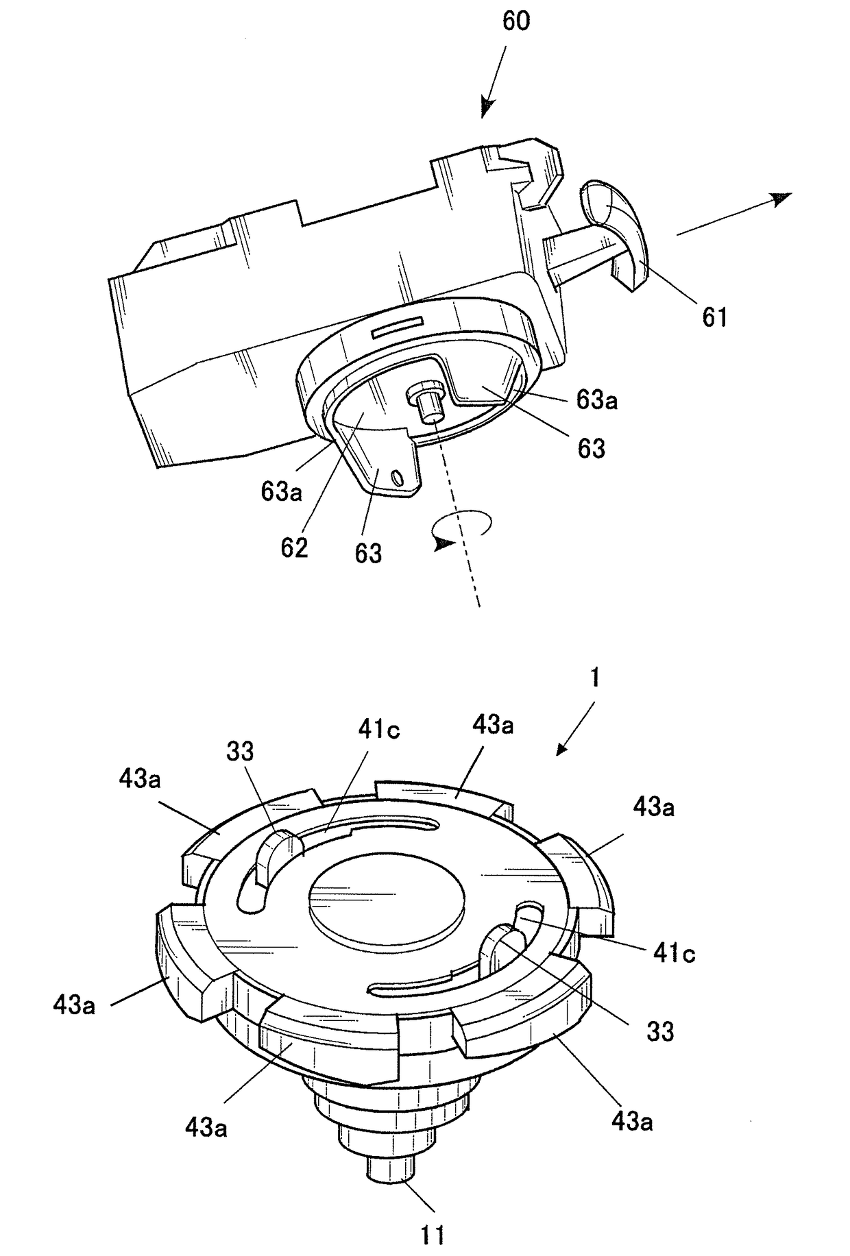
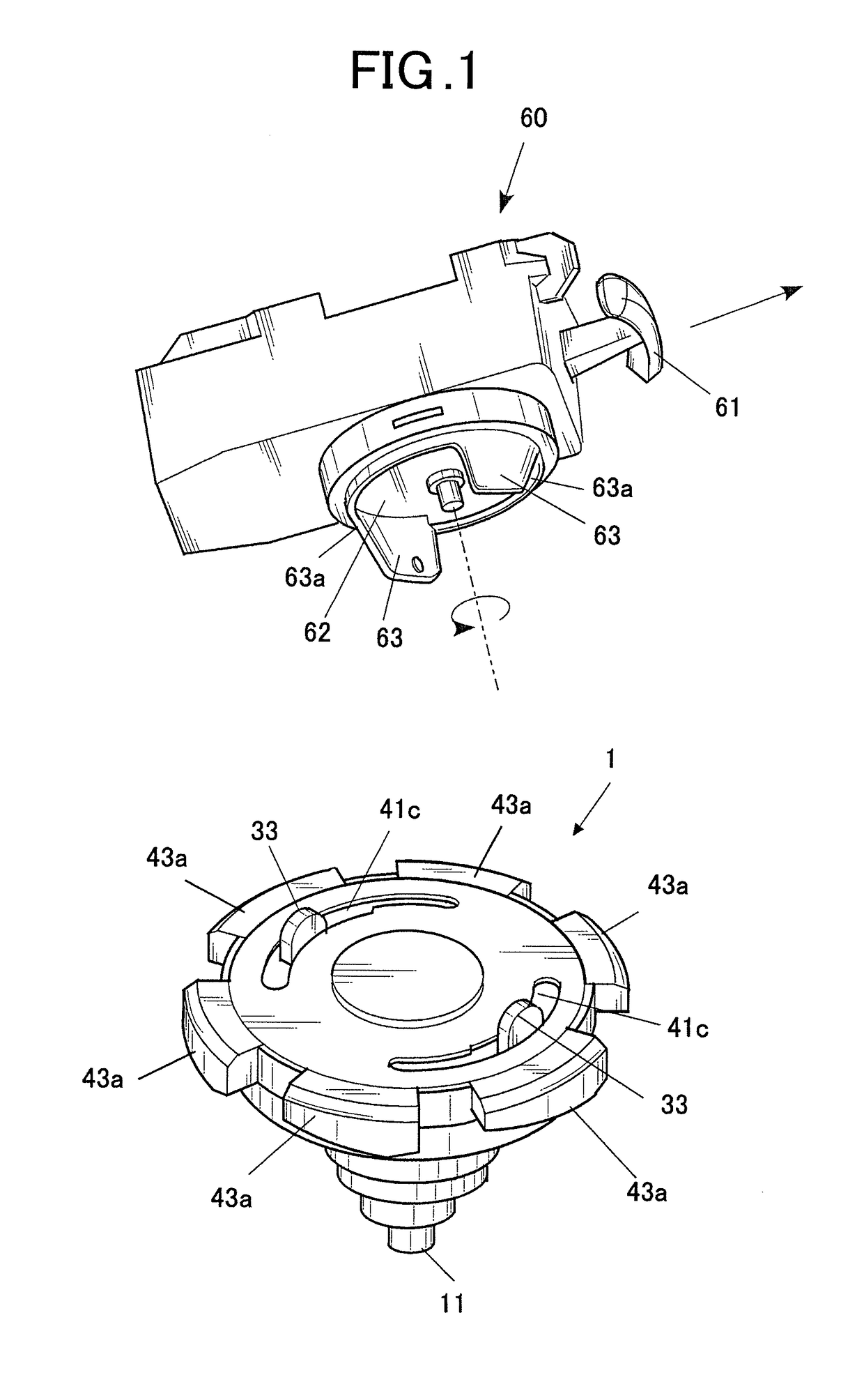
[0036]FIG. 1 illustrates a toy set composed of a toy top 1 and a launcher 60.

[0037]The toy top 1 can be used in a so-called battle game. For example, the toy top 1 is used in a battle game in which toy tops are forced to collide with each other to disassemble an opponent's toy top 1, as illustrated in FIG. 2, by an impact force.

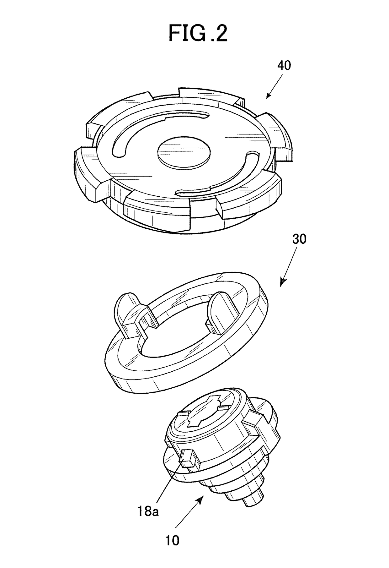
[0038]As illustrated in FIG. 3 and FIG. 4, the toy top 1 is composed of a shaft portion 10, a flywheel 30 and a body 40. While FIG. 3 and FIG. 4 illustrate a half section of the toy top 1, the unshown half is symmetric about the center axis X. As used herein, the terms up-down, right-left and front-rear refer respectively to the directions as illustrated in FIG. 4.

[0039]As illustrated in FIG. 4, the shaft portion 10 includes a spinning shaft 11 at a lower end, a flange 12 in a middle in the up-down direction, and a cylinder 13 at an upper end.

[0040]The flange 12 and the cylinder 13 are preferably integrally formed with each other. In the center of the cylind...

second embodiment

[0078]FIG. 12 illustrates guide grooves of a toy top according to a Each of the guide grooves 50 of the toy top includes an inclined groove portion 50a that is located in the spinning front side, and a gently inclined groove portion 50b that is located in the spinning rear side and has a gentler slope than the inclined groove portion 47a described above. The inclined groove portion 50a and the gently inclined groove portions 50b are upward slopes toward the spinning rear side.

[0079]With the inclined groove portions 50a and the gently inclined groove portions 50b, the guide grooves 47 of this alternate embodiment have the following functions and advantageous effects.

[0080]In the inclined groove portions 50a, the bumps 43a in the upper position descend more readily in the late stage where the toy top 1 spins at low speed. Once the bumps 43a reach the lowest position, the toy top 1 can keep spinning for a long time since the center of gravity is at a stable position. In the gently inc...


PUM


Abstract

A toy top includes a body and a bump for attack which is disposed on a circumference of the body. The bump moves up and down according to a force acting on the bump while the toy top spins.

Description

BACKGROUND OF THE INVENTION1. Field of the Invention[0001]The present invention relates to a toy top.2. Description of Related Art[0002]A battle game using toy tops that has been known in the art involves forcing toy tops to collide with each other so that a resultant impact force stops the spinning of an opponent toy top or knocks out or disassembles the opponent toy top.[0003]Some of such toy tops are designed to include attack and the defense structures that are changeable. For example, an attachment with a bump is attached to a toy body, and the bump has such a shape that allows changing the attack or the defense (e.g. see Japanese Utility Model No. 3083443).[0004]The attachment disclosed in Japanese Utility Model No. 3083443 is designed to impart different attack and defense according to whether it is attached in the face-up or face-down position, so that the attack and the defense are changeable by attaching it in the flipped position. However, flipping the attachment can be t...

Claims


Application Information

Patent Timeline
IPC IPC(8): A63F9/16A63F3/00A63H1/02A63H1/00
CPCA63F9/16A63F3/00895A63H1/02A63H1/00A63H1/04
Inventor HASHIBA, KENTA
Owner TOMY CO LTD
Features
  • Generate Ideas
  • Intellectual Property
  • Life Sciences
  • Materials
  • Tech Scout
  • Unparalleled Data Quality
  • Higher Quality Content
  • 60% Fewer Hallucinations
Learn More