Rotating drum of a tire, wheel, and/or chassis test stand

a technology of chassis and rotating drum, which is applied in the direction of vehicle testing, structural/machine measurement, instruments, etc., can solve the problems of comparatively lower energy consumption and achieve the effect of keeping time and costs

Active Publication Date: 2018-08-16
ZF FRIEDRICHSHAFEN AG
View PDF7 Cites 0 Cited by
  • Summary
  • Abstract
  • Description
  • Claims
  • Application Information

AI Technical Summary

Benefits of technology

[0004]An objective of the present invention is to keep the time and costs entailed for renewing the coating or lining of the running surface of a rotating drum as low as possible.

Problems solved by technology

Since during test operation the rotating drum is regularly accelerated and decelerated, this results in comparatively lower energy consumption.

Method used


Image

  • Rotating drum of a tire, wheel, and/or chassis test stand
  • Rotating drum of a tire, wheel, and/or chassis test stand
  • Rotating drum of a tire, wheel, and/or chassis test stand

Examples


Embodiment Construction

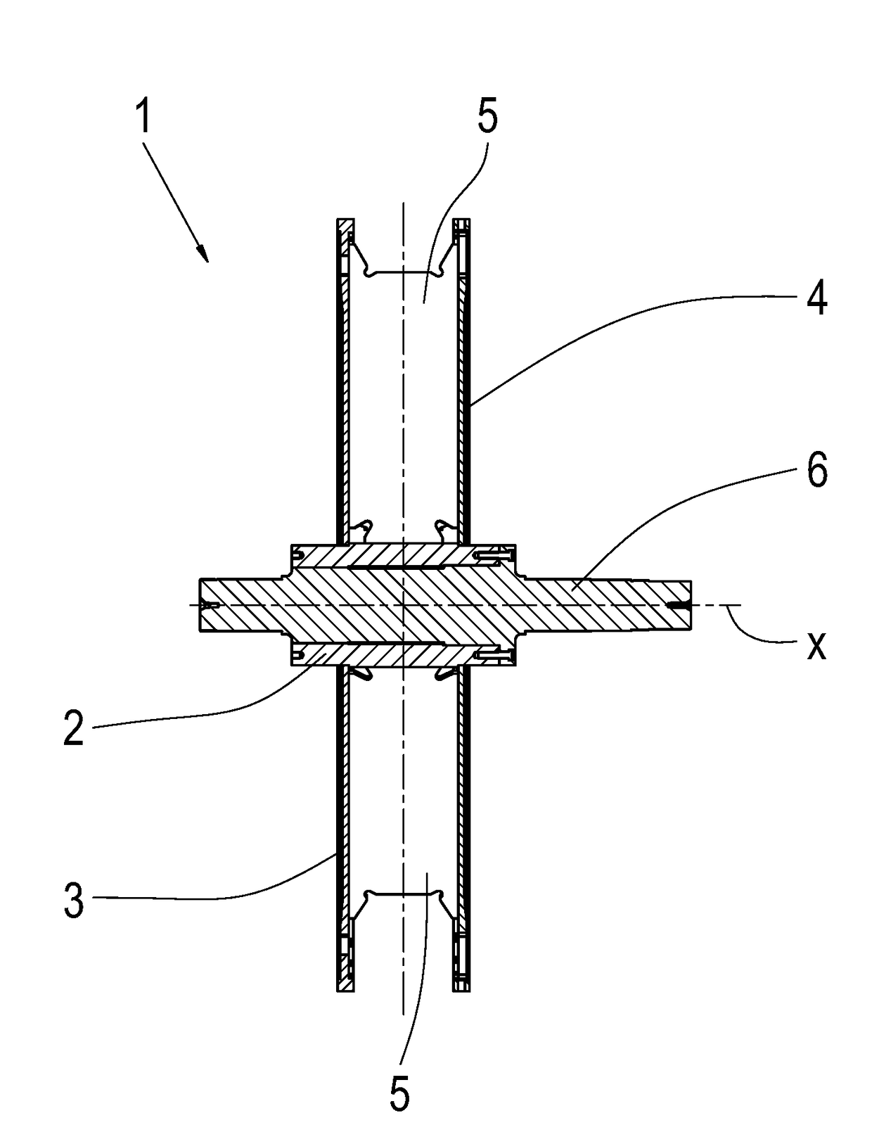
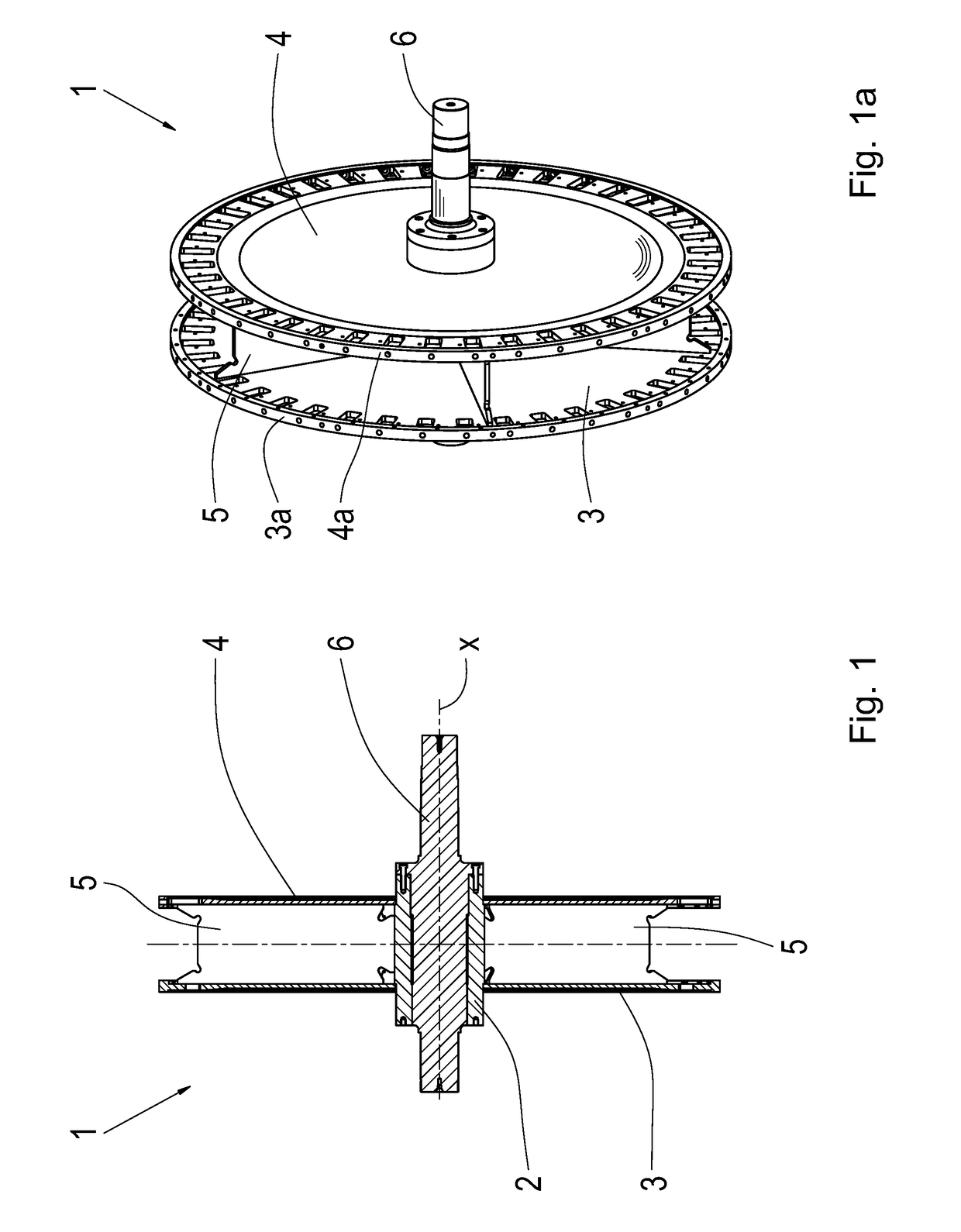
[0031]FIG. 1 shows an axial section of a rotating drum 1 according to the invention without segments, which are not shown here (compare FIG. 2). The (incomplete) rotating drum 1 shown in FIG. 1 comprises a hub 2, on which two mutually parallel side disks 3, 4 are arranged a distance apart. Between the two side disks 3, 4 stiffening elements in the form of ribs or rib plates 5 are arranged, which are connected to both side disks 3, 4 and also optionally to the circumference of the hub 2. The hub 2 is attached fixed both rotationally and axially to a driveshaft 6 with a rotational axis x.

[0032]FIG. 1a shows the rotating drum 1 represented in 3-D, wherein the two mutually parallel side disks 3, 4, the rib plates 5 and the driveshaft 6 can be seen clearly. At their circumference the side disks 3, 4 have respective first cylindrical joining surfaces 3a, 4a.

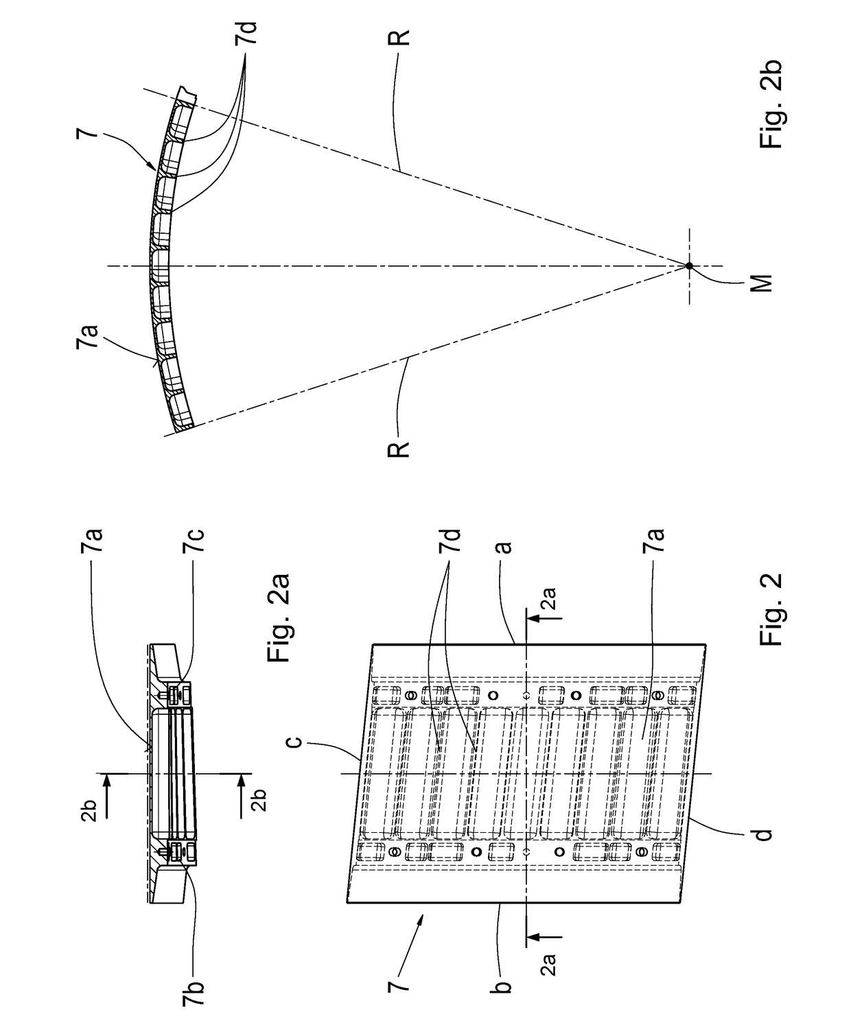
[0033]FIG. 2 shows a segment 7 according to the invention, as viewed from above, i.e. in the direction toward the rotational axis of...


PUM


Abstract

A rotating drum of a fire, wheel and/or chassis test stand, with an essentially cylindrical running surface (15). The rotating drum of a tire having a hub, side disks arranged on the hub, which in the area of their circumference (3a, 4a) have fixing areas, and a plurality of segments (7) which form the running surface (15) of the rotating drum (1,21). The plurality of segments (7) are arranged on the circumference (3a, 4a) of the fixing areas and are connected to the side disks.

Description

[0001]This application is a National Stage completion of PCT / EP2016 / 072781 filed Sep.26, 2016, which claims priority to German patent application serial no. 10 2015 220 674.2 filed Oct. 22, 2015.FIELD OF THE INVENTION[0002]The invention relates to a rotating drum of a tire, wheel and / or chassis test stand, with an essentially cylindrical running surface.BACKGROUND OF THE INVENTION[0003]Test stands for tires are known, for example from DE 10 2009 002 169 A1 by the present applicant. A vehicle wheel, i.e. a tire fitted onto a wheel rim, which is held in a wheel suspension device, runs on a running surface that simulates the road, which surface is formed by the circumference of a rotating drum. The rotating drum is stationary and arranged to rotate on an axle, and is driven in its rotational direction to produce circumferential speeds of the running surface that correspond to the speeds of the vehicle. The wheel suspension device, which is modeled on a chassis, presses the wheel with r...

Claims


Application Information

Patent Timeline
Patent Type & Authority Applications(United States)
IPC IPC(8): G01M17/02G01M17/007
CPCG01M17/022G01M17/0074
Inventor DWOLINSKI, THOMAS
Owner ZF FRIEDRICHSHAFEN AG
Why Eureka
Try Eureka