System comprising an autonomous mobile device and a base station communicating via a boundary wire

a technology of autonomous mobile devices and boundary wires, which is applied in the direction of vehicle position/course/altitude control, process and machine control, instruments, etc., can solve the problems of cumbersome adjusting of operating times, mowing height or other parameters of operation and the inability to adjust the settings of such an autonomous mobile device in response to changes in the environment, so as to improve the security of the entire system, the connection data source can be considered, and the effect of increasing

Active Publication Date: 2020-07-16
HONDA RES INST EUROPE
View PDF3 Cites 3 Cited by
  • Summary
  • Abstract
  • Description
  • Claims
  • Application Information

AI Technical Summary

Benefits of technology

[0006]Thus, it is an object of the present invention to improve the adaptivity of a system comprising an autonomous mobile device using a boundary wire to limit its working area, while at the same time keeping an eye on the product costs.

Problems solved by technology

Although the known systems of course are able to fulfill basic working tasks, they lack flexibility.
Adjusting operating times, mowing height or other parameters of operation of such an autonomous mobile device is cumbersome because it is required to input these parameters into the mobile device.
But adjusting the settings of the autonomous mobile device in response to changes in the environment, like for example children playing on the lawn, is practically impossible, if it cannot be performed from remote.
On the other side, most of such autonomous mobile devices are consumer products and thus production cost plays an important role.
One exemplary situation can be that the autonomous mobile device is being stuck.
“Move to Wi-Fi range of house network” may either cause the autonomous mobile device to move to an area that was pre-programmed during setup of the system and that is known to be covered by the house network, or it may cause the autonomous mobile device to move around within the work area and search for the house network and to stop when a connection to the house network can be successfully established.

Method used


Image

  • System comprising an autonomous mobile device and a base station communicating via a boundary wire
  • System comprising an autonomous mobile device and a base station communicating via a boundary wire
  • System comprising an autonomous mobile device and a base station communicating via a boundary wire

Examples


Embodiment Construction

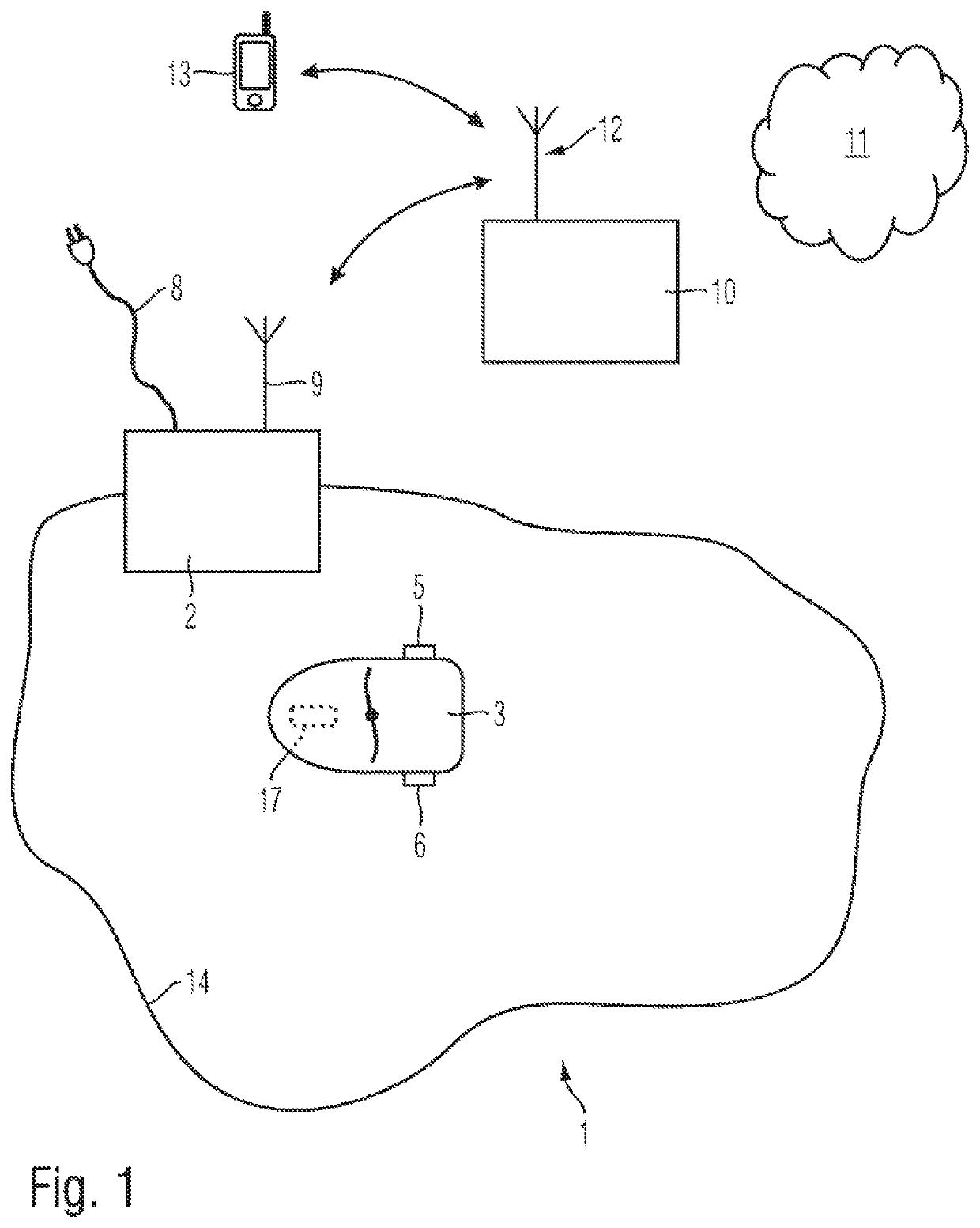
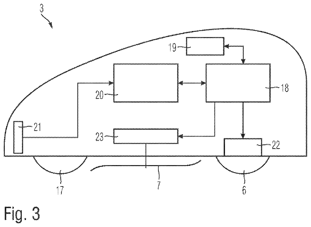
[0029]According to a preferred embodiment of the present invention, the components of the invention will now be described with reference to an autonomous lawnmower as an autonomous mobile device. The inventive system 1 comprises a base station 2 and the autonomous lawnmower 3. The autonomous lawnmower 3 is driven using at least a pair of driven wheels 5, 6 and a freely rotating wheel. Typically each of the two driven wheels 5, 6 is driven by an electric motor (not shown in the drawing) and the direction of the autonomous lawnmower 3 is controlled by generating speed differences between the wheels 5, 6. Further, only schematically shown in the figure, the autonomous lawnmower comprises a blade 7 as a working tool. The autonomous lawnmower 3 comprises a rechargeable battery (not shown in the drawing) as a power supply for the electric motors of the wheels 5, 6 but also of the motor driving the blade 7. Further components will be described later on with reference to FIG. 3, in which a ...


PUM


Abstract

A system comprising an autonomous mobile device and a base station connected to a boundary wire is configured to transmit information from the base station to the autonomous mobile device. The base station is configured to generate a radio signal to be emitted by the boundary wire, wherein the autonomous mobile device is configured to autonomously drive within a working area based on the signal emitted by the boundary wire. The base station on the other hand is configured to encode data and / or commands into the radio signal which is then emitted by the boundary wire. The autonomous mobile device receive the emitted radio signal and is configured to decode the encoded data and / or commands in order to retrieve the original information.

Description

BACKGROUNDField[0001]The invention relates to a system comprising an autonomous mobile device and a base station that is connected to a boundary wire, wherein the base station is configured to generate a radio signal to be emitted by the boundary wire and the autonomous device is configured to autonomously move within a working area based on the signal emitted by the boundary wire.Description of the Related Art[0002]Autonomous mobile devices have become more and more popular over the last years. Such autonomous mobile devices are capable of executing a working task thereby assisting a person to fulfill such working task. One example of such an autonomous mobile device is an autonomous lawnmower, but of course, there are a plurality of different autonomous mobile devices useful to assist us in our daily life. Further examples are vacuum cleaners, garden robots, storage robots. It is in particular known for outdoor robots that the working area where the autonomous mobile device shall ...

Claims


Application Information

Patent Timeline
Patent Type & Authority Applications(United States)
IPC IPC(8): A01D34/00G05D1/02
CPCG05D1/0225G05D2201/0208A01D34/008G05D1/0265G05D1/0219G08C17/02
Inventor EINECKE, NILSREBHAN, SVEN
Owner HONDA RES INST EUROPE
Why Eureka
Try Eureka