Infrared imaging device, control method thereof, and vehicle

Active Publication Date: 2018-08-16
FUJIFILM CORP
View PDF0 Cites 10 Cited by
  • Summary
  • Abstract
  • Description
  • Claims
  • Application Information

AI Technical Summary

Benefits of technology

[0030]In a far-infrared imaging device, a control method thereof, and a vehicle of the present invention, a first imaging unit which captures far-infrared rays and a second imaging unit which captures at least one of near-infrared rays and visible light, which has, for example, a wavelength shorter than a wavelength of the far-infrared rays are used. In the first imaging unit, processing for acquiring data used in unevenness c

Problems solved by technology

However, since the far-infrared imaging device is generally expensive, two far-infrared imaging devices or more are provided, and thus, it is disadvantageous in respect to costs.
However, the acquisition of the fixed pattern noise data in the far-infrared imaging device is not considered in JP2

Method used


Image

  • Infrared imaging device, control method thereof, and vehicle
  • Infrared imaging device, control method thereof, and vehicle
  • Infrared imaging device, control method thereof, and vehicle

Examples


Example

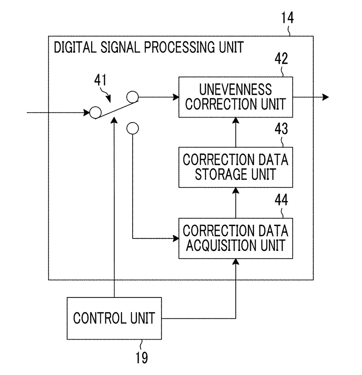
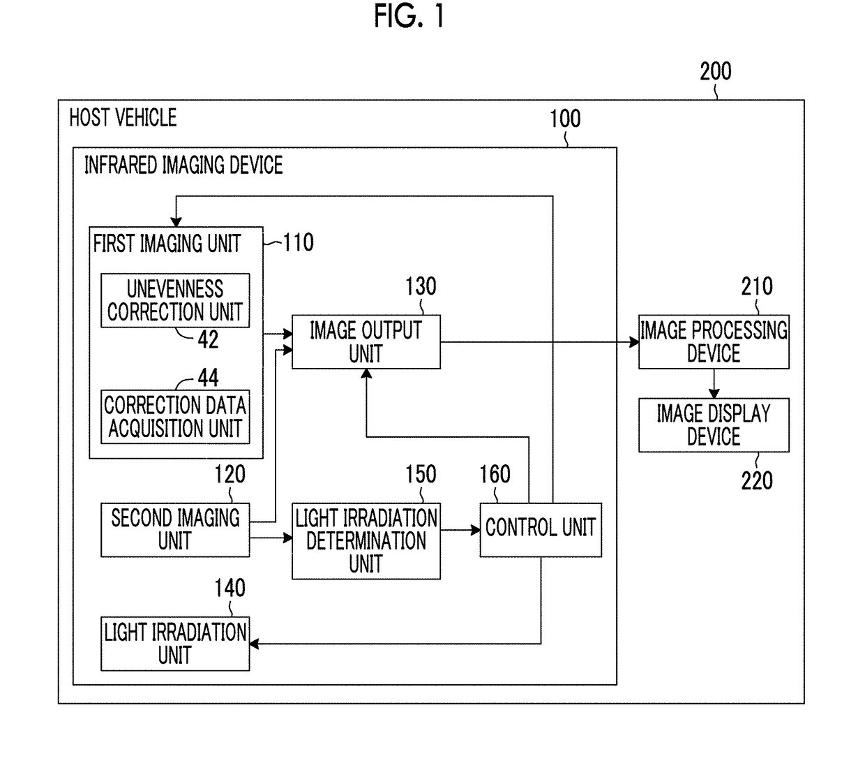
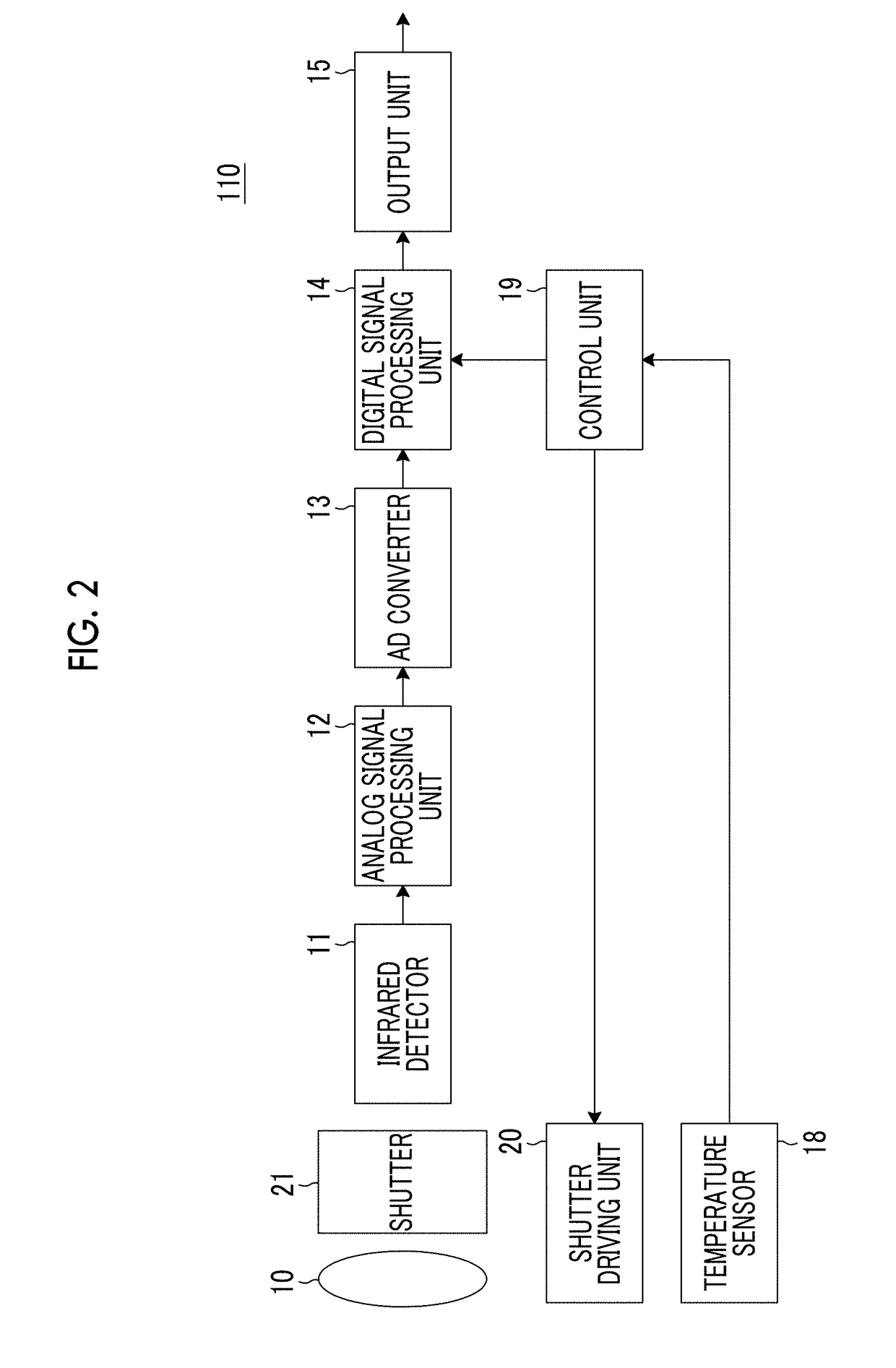
[0089]Next, a second embodiment of the present invention will be described. A configuration of an infrared imaging device according to the second embodiment of the present invention may be the same as the configuration of the infrared imaging device 100 according to the first embodiment shown in FIG. 1. In the present embodiment, the light irradiation determination unit 150 determines whether or not the second imaging unit 120 is also irradiated with the light for a period during which the correction data acquisition processing is performed in the first imaging unit 110. In a case where the light irradiation determination unit 150 determines that the second imaging unit 120 is irradiated with the light before the correction data acquisition processing is completed, the control unit 160 stops the correction data acquisition processing. Other points may be the same as those of the first embodiment.

[0090]FIG. 7 is a flowchart showing an operation procedure of the infrared imaging devic...


PUM


Abstract

A first imaging unit detects far-infrared rays and captures a first image. A second imaging unit detects light having a wavelength range shorter than a wavelength range of the far-infrared rays and captures a second image. An unevenness correction unit performs unevenness correction processing on the first image. A correction data acquisition unit acquires correction data for correcting unevenness. A light irradiation determination unit determines whether or not the second imaging unit is irradiated with light having a wavelength range captured by the second imaging unit. A control unit causes the correction data acquisition unit to acquire the correction data in a case where the light irradiation determination unit determines that light irradiation is not performed on the second imaging unit.

Description

CROSS-REFERENCE TO RELATED APPLICATIONS[0001]This application is a Continuation of PCT International Application No. PCT / JP2016 / 080454 filed on Oct. 14, 2016, which claims priority under 35 U.S.C § 119(a) to Japanese Patent Application No. 2015-210533 filed on Oct. 27, 2015. Each of the above application(s) is hereby expressly incorporated by reference, in its entirety, into the present application.BACKGROUND OF THE INVENTION1. Field of the Invention[0002]The present invention relates to an infrared imaging device, and more particularly, to an infrared imaging device having an infrared detector that detects incident infrared rays and converts the detected infrared rays into electric signals. Further, the present invention relates to a control method of the infrared imaging device. Furthermore, the present invention relates to a vehicle having the infrared imaging device mounted thereon.2. Description of the Related Art[0003]An infrared imaging device that detects incident infrared l...

Claims


Application Information

Patent Timeline
IPC IPC(8): H04N5/33G01J5/10G01J5/08H04N5/365H04N5/353
CPCH04N5/33G01J5/10G01J5/0834H04N5/3653H04N5/353B60R1/00B60R2300/301G01J2005/0077H04N7/18G08G1/165G08G1/166B60R2300/103H04N23/667H04N25/672G01J5/0804H04N25/53
Inventor KOBAYASHI
Owner FUJIFILM CORP
Why Eureka
Try Eureka