
Illumination control device of surgical light

a control device and light technology, applied in the direction of fixed installation, lighting and heating equipment, support devices, etc., can solve the problems of increased risk of infection, increased time required for operating the control interface, and additional human labor of medical personnel, so as to reduce the risk of infection and expenditure of patients, the effect of improving the efficiency of surgical operations

Inactive Publication Date: 2018-08-23
AMTAI MEDICAL EQUIP
View PDF0 Cites 9 Cited by
  • Summary
  • Abstract
  • Description
  • Claims
  • Application Information

AI Technical Summary

Benefits of technology

The present invention allows surgeons to use their hands to control the illumination during surgical procedures, even if they are not able to control it themselves. This is done by detecting the signals from an infrared transmitter reflected back to an infrared receiver. A compensation control mechanism is provided for temperature compensation and management of operation frequencies of the detection pairs. This improves the efficiency of surgical operations and reduces the risk of infection and expenditure for patients.

Problems solved by technology

Firstly, the control interface is mounted in a sterile area of a surgical room. If a surgeon is allowed to operate it during the process of a surgical operation, there might potential risk of infection of the patient. Thus, the surgeons must instruct other medical personnel located outside the sterile area to operate the control interface in order to control the illumination. Thus, the surgeons must wait for the operation of the control interface by the medical personnel to be completed before the lighting necessary for illumination can be obtained. This makes it necessary to have other medical personnel stand by during the process of the surgical operation, leading to the time required for operating the control interface extended for achieving proper adjustment and control of the lighting, and additional human labor of medical personnel must be involved.
Secondly, the control interface is generally mounted at a location very close to an operation area of a surgical room. If medical personnel who are in a condition of proper disinfection are allowed to operate the control interface, then contaminant, bacteria, or virus carried on their suits may entrain air streams that flow downward from the ceiling of the surgical room to get into the incision openings of the patient, leading to an increase of the potential risk of infection.
Thirdly, some surgical operations may be conducted collaboratively by multiple surgeons and the sterile areas around the surgical table would be full of medical personnel including surgeons, anesthetists, and nurses, making it not possible for other medical personnel to get approaching the light heads of the surgical light that are generally located above the surgical table for operating the control interface. This makes it necessary to install a wall-mounted control interface for the surgical room to allow for access and operation of the control interface from outside the sterile area by the other medical personnel. This makes it not possible to save the cost of installation and wire laying of the wall-mounted control interface.
Since the cylindrical projection formed under the light head of the surgical light and the pushbutton mounted thereon are located in an unsterilizable area, surgeons and / or medical personnel are not allowed to directly contact it.
This increases the expenditure of the consumable material for surgical operations.
Further, additional cost of installation and wire laying for a wall-mounted control interface is also required.

Method used


Image

  • Illumination control device of surgical light
  • Illumination control device of surgical light
  • Illumination control device of surgical light

Examples


Embodiment Construction

[0029]The following descriptions are exemplary embodiments only, and are not intended to limit the scope, applicability or configuration of the invention in any way. Rather, the following description provides a convenient illustration for implementing exemplary embodiments of the invention. Various changes to the described embodiments may be made in the function and arrangement of the elements described without departing from the scope of the invention as set forth in the appended claims.

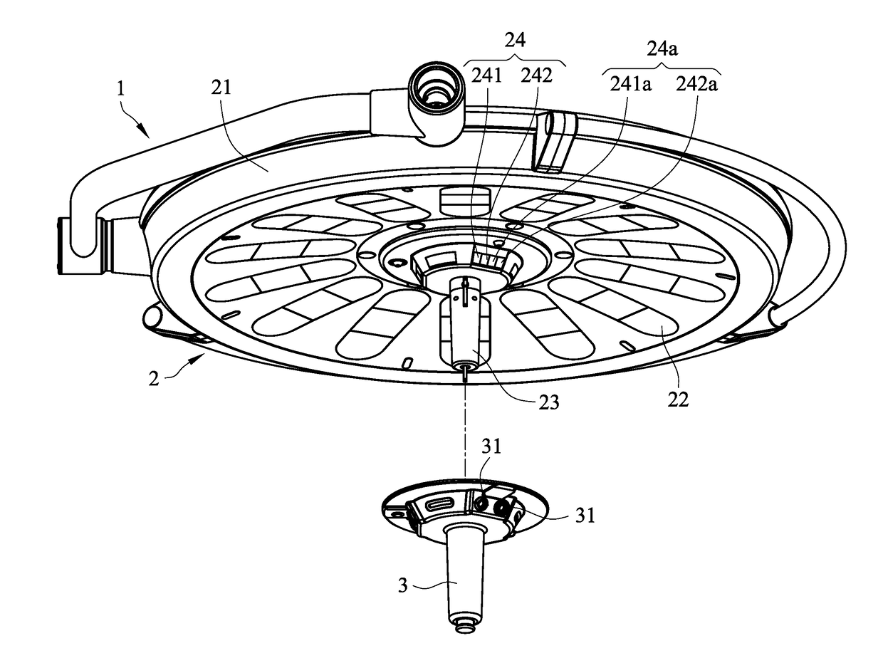
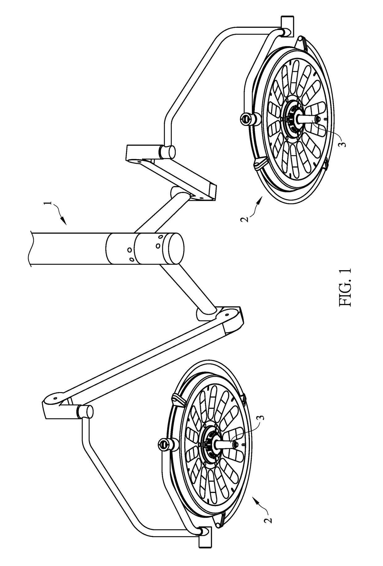
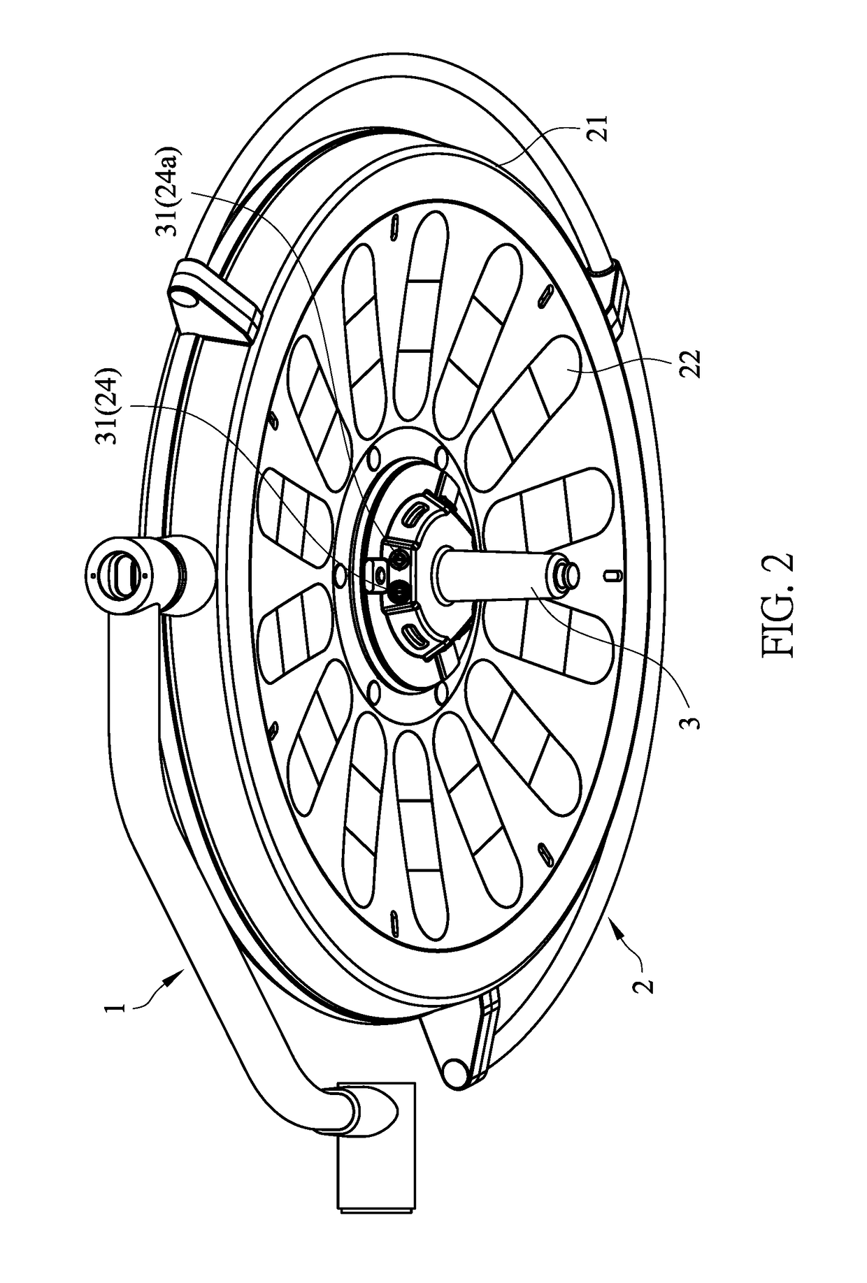
[0030]Referring to FIGS. 1-5, which are respectively a schematic view illustrating an entire arrangement of the present invention, a perspective view showing a light head of the arrangement of the present invention, an exploded view of the light head of the arrangement of the present invention, a bottom view of the light head of the arrangement of the present invention, and a block diagram illustrating a compensation control mechanism of the present invention, as shown in the drawings, the present i...


PUM


Abstract

A surgical lighting illumination control device includes a suspension system; light heads mounted on the suspension system and each including a housing, light sources mounted in the housing, an unsterilizable grip mounted on the housing for hand holding and moving the light heads, and detection pairs mounted to the unsterilizable grip for receiving an infrared signal that is transmitted therefrom and reflected by an external object for control and adjustment of the illumination, each detection pair including an infrared transmitter and an infrared receiver; a compensation control mechanism connected to the detection pairs and including a control operation unit and environment temperature compensation units connected to the control operation unit; and a sterilizable grip mountable to the unsterilizable grip and including a guide channel formed therein to correspond, in position, to each of the detection pairs to allow the infrared signal to pass therethrough.

Description

CROSS-REFERENCE TO RELATED APPLICATION[0001]This is a continuation-in-part of co-pending U.S. patent application Ser. No. 15 / 058,159 filed on Mar. 2, 2016.(a) TECHNICAL FIELD OF THE INVENTION[0002]The present invention relates generally to innovation associated with an illumination control device of surgical light, and more particularly to one allowing surgeons to control, during the process of a surgical operation, the illumination by themselves to instruct medical personnel to control the illumination from a location outside a sterile area by means of an infrared remote controller so as to improve the efficiency of surgical operations and reduce patients' risk of infection and also reduce the expenditure of manufacture.(b) DESCRIPTION OF THE PRIOR ART[0003]US Patent Application Publication No. 2007 / 0030702 describes techniques that a control interface for operating an illumination function of a surgical light is mounted to a suspension arm thereof at a location close to a light he...

Claims


Application Information

Patent Timeline
IPC IPC(8): F21V23/04F21V21/40F21V21/28H05B37/02F21V23/00A61B90/35
CPCF21V23/0435F21V21/40F21V21/28H05B37/02F21V23/003A61B90/35F21W2131/205A61B2090/308F21S8/043F21S8/063F21V23/045A61B2017/00212H05B47/10H05B47/13Y02B20/40
Inventor LIANG, CLAYWU, WEI-LITSENG, CHIH-CHENG
Owner AMTAI MEDICAL EQUIP
Learn More