Respiratory therapy filter, flow control, and patient interface apparatuses, systems, and methods
What is AI technical title?
AI technical title is built by Patsnap AI team. It summarizes the technical point description of the patent document.
a technology of flow control and respiratory therapy, applied in the field of respiratory therapy, can solve the problems of adding cost, size and weight to the respiratory device, and achieve the effect of improving the efficiency of respiratory therapy
Active Publication Date: 2018-08-30
HILL ROM SERVICES
View PDF3 Cites 12 Cited by
Summary
Abstract
Description
Claims
Application Information
AI Technical Summary
This helps you quickly interpret patents by identifying the three key elements:
Problems solved by technology
Method used
Benefits of technology
Benefits of technology
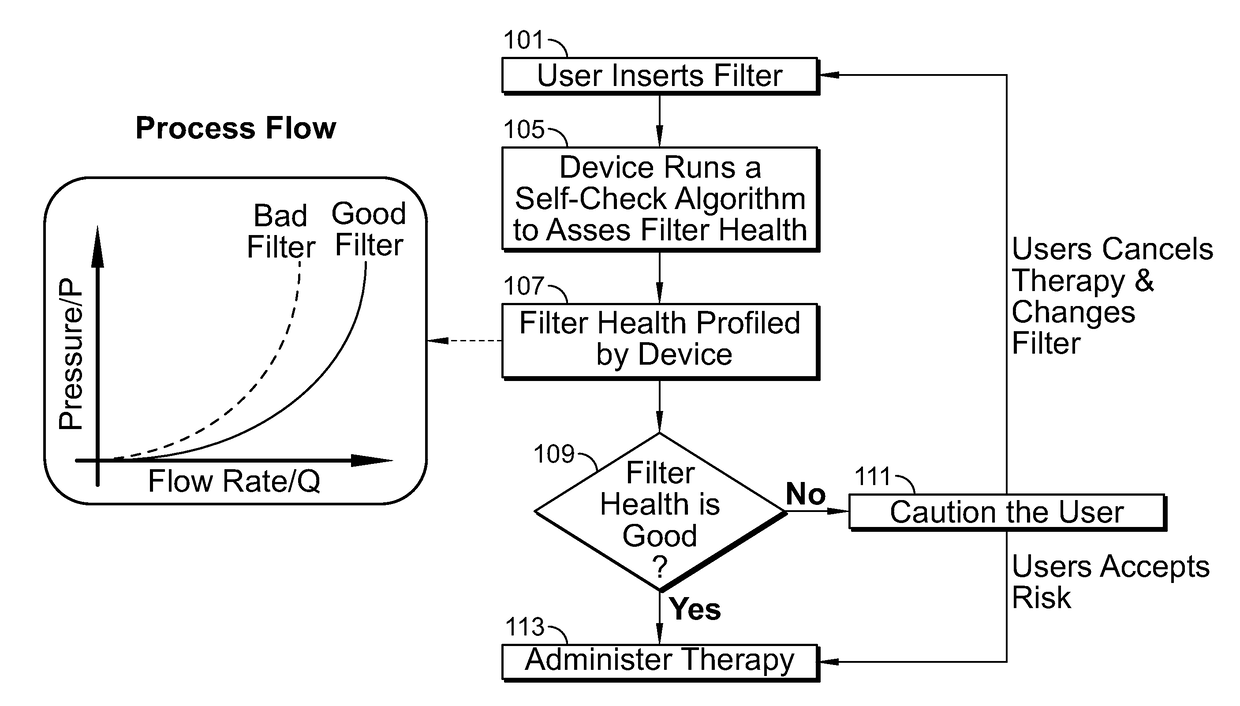
The present patent describes a respiratory device with a housing and a filter that can be attached to the housing. The device includes a magnetic proximity switch that is positioned near the hose port and is activated when the filter is attached to the hose port. The device also includes an indicator that is activated when the magnetic proximity switch is activated. The technical effect of this feature is to provide a convenient and reliable way to verify that the filter is properly attached to the device.
Problems solved by technology
These additional structural elements to produce the oscillations add cost, size and weight to the respiratory device.
Method used
Image
Click on the blue label to locate the original text in one second.
Reading with bidirectional positioning of images and text.
Examples
Embodiment Construction
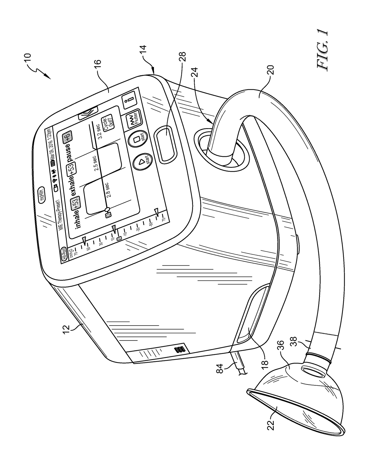
[0063]A respiratory device 10 is provided. The details of the structure of a suitable respiratory device and related electrical components may be found in International Application No. PCT / SG2016 / 050166, filed Apr. 1, 2016, published as WO 2016 / 159889 A1 on Oct. 6, 2016, and titled “Manifold for Respiratory Device,” which is hereby incorporated herein in its entirety. Respiratory device 10 includes a housing 12 having a front wall 14 on which a display or graphical user interface 16 is accessible to enter user inputs into device 10 and to view displayed information regarding the operation of device 10 as shown in FIG. 1. Housing 12 is configured with a handle 18 at its bottom which is gripped by a person to carry device 10. At a bottom region of front wall 14 of housing 12, a hose 20 of a patient interface 22 is attached to a hose port 24. Beneath the graphical user interface 16 there is an on / off button 28 that is pressed sequentially to turn device 10 on and off.
[0064]Device 10 is...
PUM
Abstract
A nebulizerassembly for a respiratory device is provided having a housing defining a chamber. The housing also has a nebulizer port configured to receive a nebulizer to discharge atomized medication into the chamber. An outlet of a handle is coupled to the inlet of the housing. A hose is coupled to an inlet of the handle. A patient interface is coupled to the outlet of the housing. Air flows from the hose to the patient interface via the handle and the housing. The air mixes with the atomized medication within the chamber.
Description
CROSS-REFERENCE TO RELATED APPLICATIONS[0001]This application claims priority under 35 U.S.C. § 119 to U.S. Patent App. Ser. No. 62 / 463,806 entitled “RESPIRATORY THERAPY FILTER, FLOW CONTROL, AND PATIENT INTERFACE APPARATUSES, SYSTEMS, AND METHODS,” which was filed Feb. 27, 2017 and is expressly incorporated herein by reference.BACKGROUND[0002]The present disclosure relates to respiratory devices and particularly, to respiratory devices that are operable to apply varying levels of oscillating pressure to an airway of a patient.[0003]Respiratory devices that provide positive pressure to a person's airway are known. For example, there are Continuous Positive Airway Pressure (CPAP) devices that apply positive pressure to a person's airway at a substantially constant level during the person's inhalation and exhalation. There are also Bi-Level CPAP devices that apply varying levels of positive pressure to a person, such as applying a first amount of positive pressure during inhalation an...
Claims
Application Information
Patent Timeline
Application Date:The date an application was filed.
Publication Date:The date a patent or application was officially published.
First Publication Date:The earliest publication date of a patent with the same application number.
Issue Date:Publication date of the patent grant document.
PCT Entry Date:The Entry date of PCT National Phase.
Estimated Expiry Date:The statutory expiry date of a patent right according to the Patent Law, and it is the longest term of protection that the patent right can achieve without the termination of the patent right due to other reasons(Term extension factor has been taken into account ).
Invalid Date:Actual expiry date is based on effective date or publication date of legal transaction data of invalid patent.
Patent Type & AuthorityApplications(United States)

