Low leakage liquid atomization device

a liquid atomization device and low leakage technology, which is applied in the direction of moving spraying devices, spray nozzles, spraying apparatuses, etc., can solve the problems of liquid being atomized that is neither solid nor dimensionally stable, and cannot be applied in the foregoing patents, so as to achieve easy handling, maintain the performance of the device at a high level, and minimize the migration of liquid being atomized

Inactive Publication Date: 2005-01-18
SC JOHNSON & SON INC
View PDF21 Cites 94 Cited by
  • Summary
  • Abstract
  • Description
  • Claims
  • Application Information

AI Technical Summary

Benefits of technology

In one aspect this invention minimizes the migration of liquid being atomized so that the atomizing device itself remains dry and easy to handle. At the same time the performance of the device is maintained at a high level and no undesired leakage and loss of liquid is experienced.
According to this one aspect, there is provided a novel liquid atomizing device which comprises a source of liquid to be atomized and which is maintained at a fixed position by a support. The device also includes an atomization assembly comprising an atomization plate and a piezoelectric actuator connected to vibrate the plate. A mounting structure extends from the support to the atomization assembly to hold the atomization assembly at a predetermined location relative to the fixed position. The mounting structure is configured to have a small cross-section relative to its length to minimize migration of liquid between the atomization assembly and the support.
According to another aspect of the invention there is provided a novel liquid reservoir This novel reservoir comprises a liquid container which is removably attachable to an atomization device for delivery of a liquid to a vibrating plate in the atomization device and an elongated member having capillary passages extending from one end thereof to an opposite end. A lower region of the elongated member is solid and dimensionally stable and extends from within the liquid container out through an opening in a upper region of the container. The elongated member has a compressible upper region which is fixed to the upper end of the lower region and which is located outside the container. Because the lower region of the elongated member is solid, it may be solidly secured to the container opening with a minimum of leakage. At the same time, because the upper region of the elongated member is compressible, it will not interfere with vibrations of the vibrating plate irrespective of variations in the vertical dimensioning of the elongated member.
According to a still further aspect of the invention, there is provided a novel liquid delivery system for transferring liquid from a reservoir to a vibrating atomization plate. This novel liquid delivery system comprises a solid tubular member having a longitudinal passage extending therethrough and a solid rod which extends through the longitudinal passage. The solid tubular member and the solid rod have mutually facing surfaces which are configured to form capillary passages extending from one end of the solid rod to its other end. This novel liquid delivery system is dimensionally stable and maintains the point at which liquid is delivered to a vibratory atomization plate at a precise location so as not to interfere with the vibration of the plate.

Problems solved by technology

However, the wick is neither solid nor dimensionally stable.
None of the foregoing patents address the problem that one encounters upon atomizing liquids which are characterized by low viscosity and low surface tension which are common among fragrances, air fresheners and insecticides.
These liquids tend to migrate along the structural elements of the atomizer device and cause wetting of its various surfaces.
As a result it becomes difficult to handle the atomization device.
Further, its performance deteriorates and valuable liquid is lost without being atomized.
Further, none of the above patents discloses any arrangement to ensure that liquid is supplied to a vibrating plate from a fixed location relative to the plate in order to provide a sufficient supply of liquid without appreciably damping the vibrations of the plate.
Finally, the prior art fails to disclose any arrangements for efficiently holding a vibrating atomization plate and actuator element in a liquid atomization device.

Method used


Image

  • Low leakage liquid atomization device
  • Low leakage liquid atomization device
  • Low leakage liquid atomization device

Examples


Embodiment Construction

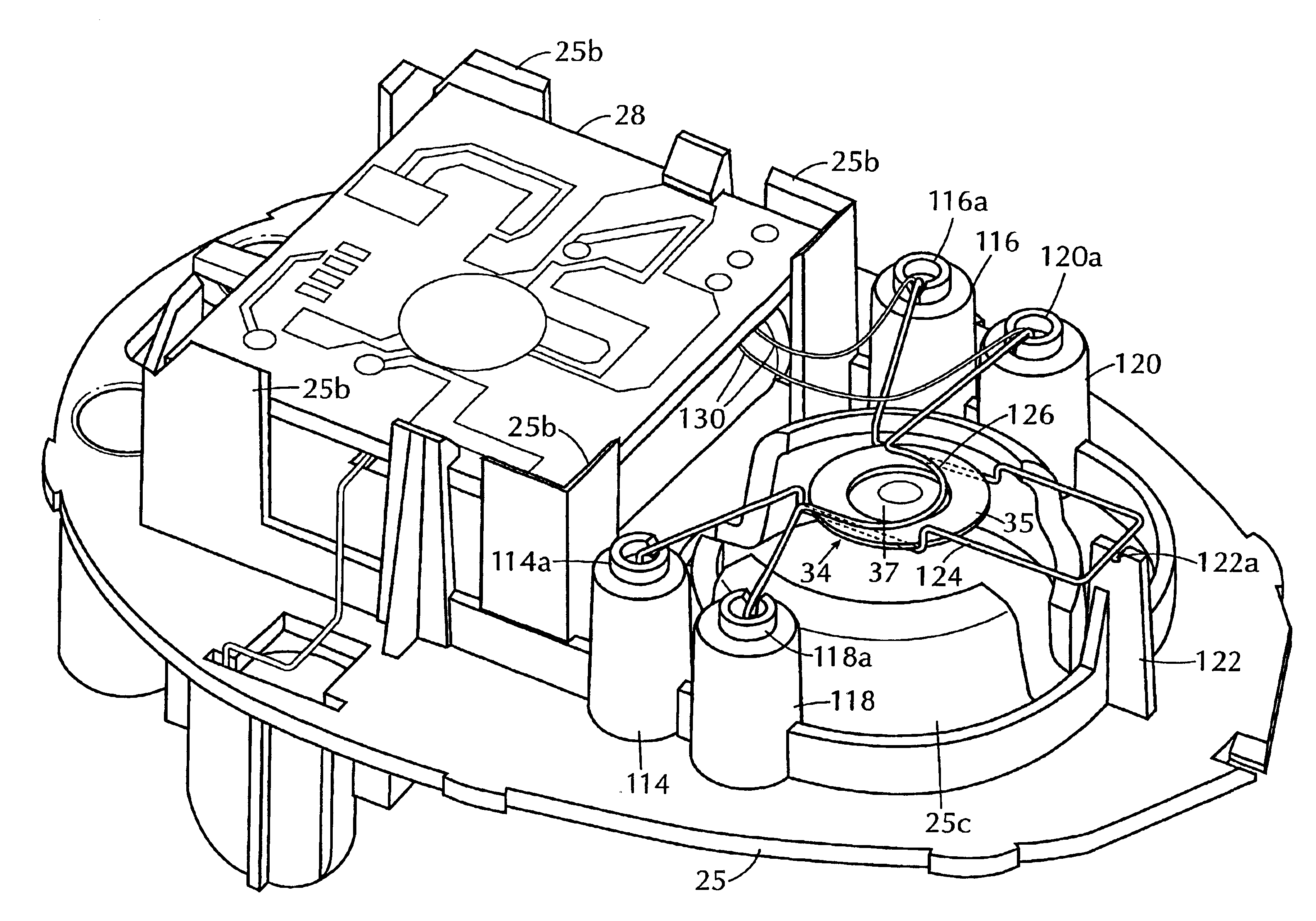
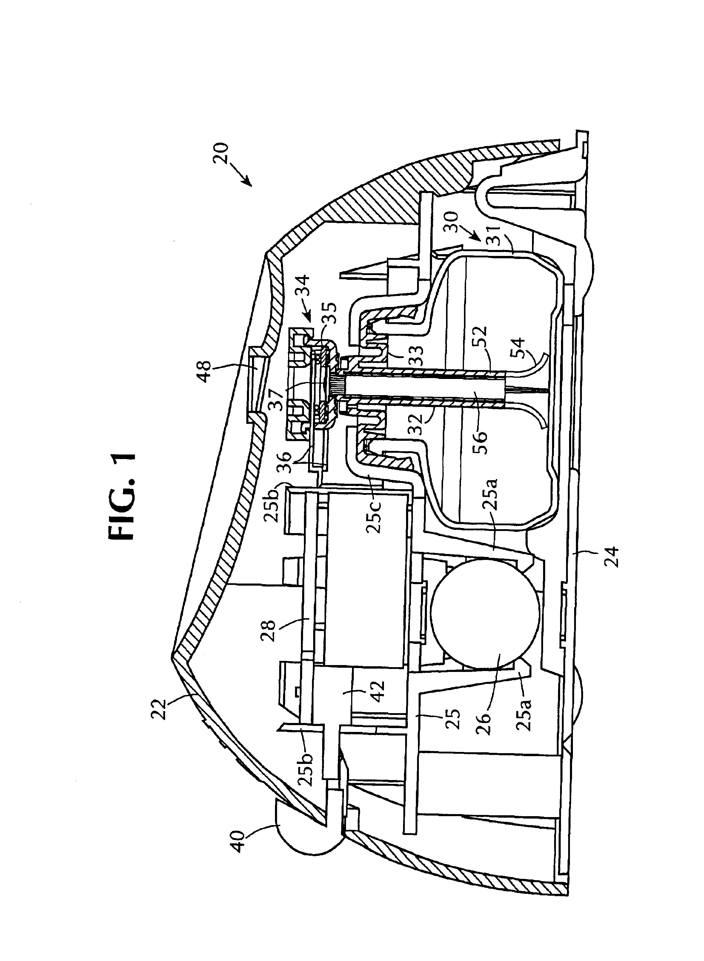
As shown in FIG. 1, a piezoelectrically actuated atomization device 20 according to the present invention comprises a housing 22 formed as a hollow plastic shell and closed by a flat bottom wall 24. A horizontal platform 25 extends across the interior of the housing 22. A battery 26 is supported by means of support prongs 25a which extend down from the underside of the platform 25 inside the housing 22. In addition, a printed circuit board 28 is supported on support elements 25b which extend upwardly from the platform 25. A liquid reservoir 30 assembly is replaceably mounted to the underside of a dome-like formation on the platform 25.

The liquid reservoir assembly 30 comprises a liquid container 31, a cap or plug 33 which closes the top of the container and a liquid delivery system 32 which extends from within the liquid container and through the cap or plug 33, to a location above the liquid container. The liquid container 31, the liquid delivery system 32 and the cap or plug 33 ar...


PUM


Abstract

A battery operated atomizer device comprising, in a housing (22), a liquid reservoir (30) from which a capillary type liquid delivery system (38) extends to contact a piezoelectric actuator an atomization plate assembly (34), the assembly (34) being supported by means of wire-like elements (36) in cantilever fashion over the liquid delivery system, the liquid delivery system comprising an outer tubular member (52) and a solid rod (56) which have facing surfaces configured to define between them, longitudinal capillary liquid passages.

Description

BACKGROUND OF THE INVENTION1. Field of the InventionThis invention relates to piezoelectrically actuated vibratory type liquid atomization devices and more particularly it relates to novel structures for such devices which are characterized by low liquid loss and high efficiency handling of liquids being atomized.2. Description of the Related ArtU.S. Pat. No. 5,758,637 to Ivri et al. shows a liquid dispensing apparatus in which a cantilever beam is attached to an electronic circuit and which bends and vibrates in response to actuation of a piezoelectric element attached to the beam. The vibration of the beam is transferred to a shell member to produce atomization of liquid supplied to the shell member. U.S. Pat. No. 5,297,734 also shows a bendable cantilever beam of piezoelectric material which is attached to an atomization plate.U.S. Pat. No. 4,119,096 to Drews shows a medical inhaler in which a transducer is mounted in cantilever fashion within the inhaler. U.S. Pat. No. 5,283,496...

Claims


Application Information

Patent Timeline
Patent Type & Authority Patents(United States)
IPC IPC(8): B05B17/04B05B17/06
CPCB05B17/0646B05B17/0684B05B17/0676B05B17/06
Inventor BOTICKI, JOHN A.BOURNOVILLE, JAMES L.LARSON, PAUL J.HELF, THOMAS A.MARTENS, III, EDWARD J.SCHRAM, DAVID J.TOMKINS, DAVID A.DOERR, STEPHEN M.JAWORSKI, THOMAS
Owner SC JOHNSON & SON INC
Why Eureka
Try Eureka