
Atomizer

Active Publication Date: 2007-03-22
BOEHRINGER INGELHEIM INT GMBH
View PDF22 Cites 91 Cited by
  • Summary
  • Abstract
  • Description
  • Claims
  • Application Information

AI Technical Summary

Benefits of technology

[0012] A primary object of the present invention is to provide an atomizer that is simple to operate and has improved safety in use.
[0014] An initial aspect of the present invention is that the counter device or at least a first counter of the counter device for counting the number of operations of the atomizer, is arranged on a housing part of the atomizer that can be detached in order to insert and / or change the container, wherein the atomizer is locked against further operation and / or against removal of the current container or insertion of a new container, if a certain number of operations of the atomizer has been reached or exceeded. The locking under these conditions is in the following also referred to as “first locked state.” The enforced locking of the atomizer on reaching or exceeding a specified number of operations of the atomizer leads to simple operation and improved safety in use, since the user, even if not noticing an optional display of the previously performed or remaining operations of the atomizer, is protected from improper operation. In particular, it is possible to prevent sucking in air from an empty or almost empty container in an undesirable manner which can, in particular, lower the dosing accuracy.
[0018] According to a second, also independently achievable, aspect of the present invention, the counter device is designed in such a way that the atomizer is locked against further operation and / or against removal of the current container or insertion of a new container, if a certain number of containers is used, and if necessary, also a certain number of operations of the atomizer with the current container have been reached or exceeded. The locking under these conditions is referred to in the following as the “second locked state.” The stated container counting and locking leads to simple operation and improved safety in use, since use of the atomizer beyond a specified, permitted number of containers is excluded without the user having to take pay attention to a display of the number of containers already used or the like.
[0019] Particular preference is in the first or second locked state for a locking element, such as a button, that is operated to trigger the delivery and / or atomization of fluid, to be locked. This makes intuitive use easier and makes it clear to the user in a simple manner that the atomizer is locked.
[0021] Alternatively or additionally, removal of the housing part of the atomizer in the first or second locked state can be locked. This, in turn, allows intuitive identification of a locked state by a user,.
[0022] According to a third, also independently achievable aspect of the present invention, the container counter device has an operating element so that the counter device can detect a movement or position of the container associated with fluid withdrawal, fluid delivery, pressurization and / or atomization and can count this as an operation of the atomizer. This leads to a particularly safe registration of operations of the atomizer, and accordingly, to safe counting. This is conducive to simple operation and improved safety in use, since faulty operation or operating errors, such as repeated operation of an operating element when the atomizer is not tensioned or without withdrawal of fluid, are not detected and counted as operations of the atomizer.

Problems solved by technology

In particular, it is possible to prevent sucking in air from an empty or almost empty container in an undesirable manner which can, in particular, lower the dosing accuracy.

Method used


Image

  • Atomizer
  • Atomizer
  • Atomizer

Examples


first embodiment

[0071] FIGS. 3 to 17 show a atomizer 1 according to the present invention. FIG. 3 shows atomizer 1 in a schematic cross-section in the delivered state. The housing upper part 16, with the pressurizer 5 and other parts of the atomizer 1, is preferably separate from the housing part 18 with the container 3 in the delivered state.

[0072]FIG. 4 shows a schematic cross-section of the housing part 18 with the container 3 in the delivered state, wherein the opening of the housing part 18 with the container 3 is covered by a protective cap 24 that can be removed for assembly purposes. The protective cap 24 supports the container 3 which is still sealed at its free end in its delivered state, which at the time of assembly is introduced into the housing upper part 16 or inner part 17. At its base end, the container 3, in this state, is axially moved away from the piercing element 22, and thus, is sealed at the base end. Preferably, the container 3 cannot be separated from the hosing part 18, b...

second embodiment

[0130] With the second embodiment, the housing part is rotatable in the opposite direction to the direction of rotation for tensioning the atomizer 1 or the drive spring 7 in a release direction for axial detachment (preferably also of the container 3). In particular, the rotation in the release direction is only possible with the atomizer 1 tensioned. On the housing part 18 and / or on the atomizer 1, a sliding surface 52, 53, is arranged or formed that is inclined relative to the axis of rotation (longitudinal axis) of the atomizer 1 or the direction of movement of the container 3. When the housing part 18 is rotated in the release direction, according to the principle of inclined planes, an axial release of the housing part 18 and preferably the container 3 from the atomizer 1 or the housing upper part 16 takes place. Accordingly, the release is simplified substantially.

[0131] In the example shown, the sliding surface 52 is formed by the diagonally cut end of the housing part 18. A...

third embodiment

[0134]FIG. 19 shows a proposed atomizer 1 according to a The housing part 18 is shown in a see-though manner for illustration purposes.

[0135] With the third embodiment, the atomization of fluid 2 preferably takes place, as in the first and second embodiments, exclusively through the force of the drive spring 7. In contrast to the first or second embodiment, however, the drive spring 7 in the third embodiment is arranged in the detachable housing part 18, and therefore, can be detached with the housing part 18 from the atomizer 1 or the housing upper part 16.

[0136]FIG. 20 shows a schematic cross-section of the housing part 18 with the drive spring 7 and the container 3 in the preferred delivered state, namely separate from the housing upper part 16, in particular with a protective cap 24 according to the first embodiment in accordance with FIG. 4. In the housing part 18, a beaker-shaped seat 56 is preferably arranged for the container 3. In the example shown, the drive spring 7 is ...


PUM


Abstract

An atomizer for a fluid, in particular, a fluid for medical aerosol therapy. In order to allow simplified operation and improved safety in use, the atomizer has a counter device for counting the number of operations of the atomizer and the number of containers inserted. The atomizer is locked against further operation and / or against removal of the current container or insertion of a new container, if a certain number of operations of the atomizer and / or a certain number of containers inserted has / have been reached or exceeded.

Description

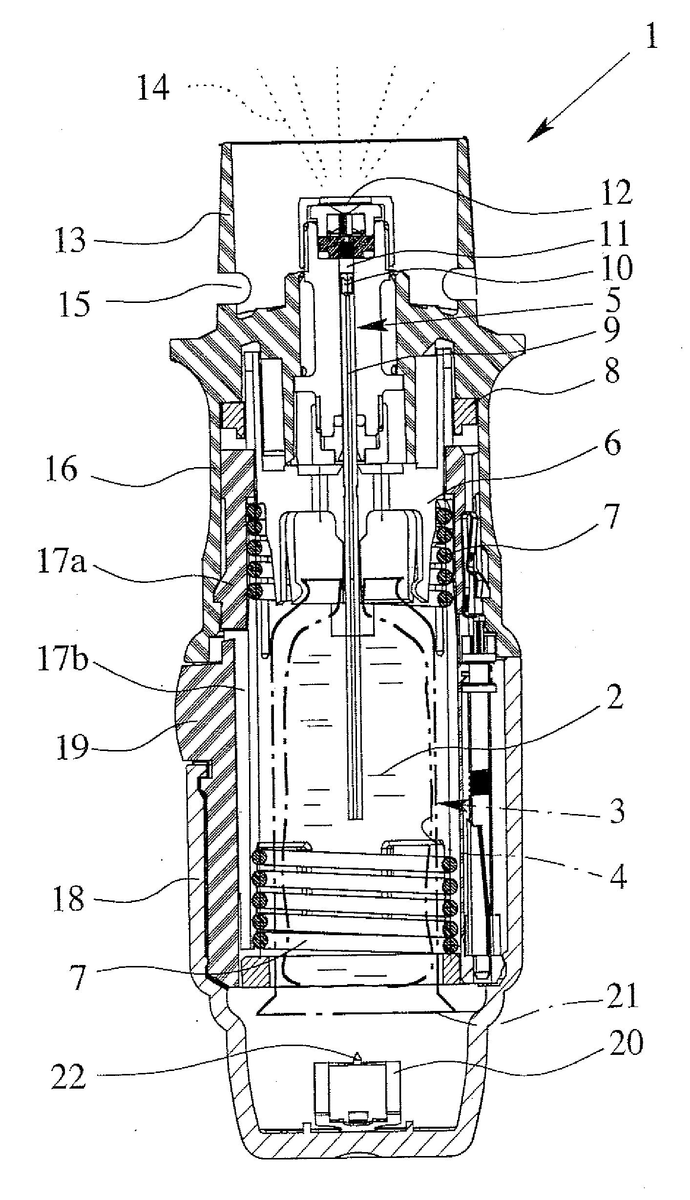
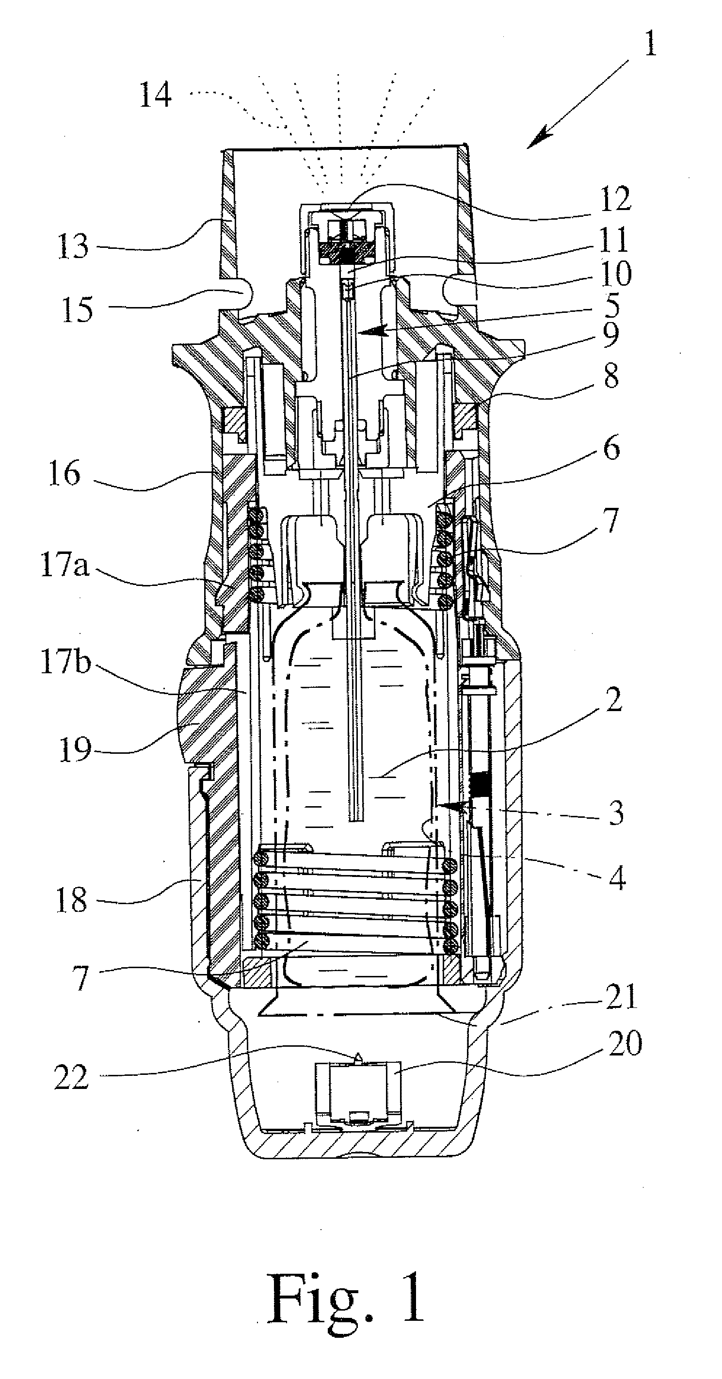
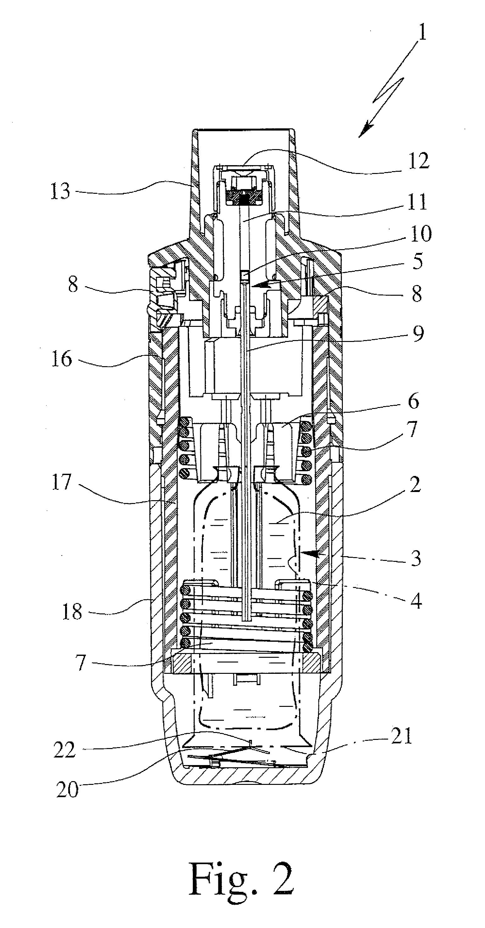
BACKGROUND OF THE INVENTION [0001] 1. Field of the Invention [0002] The present invention concerns an atomizer according to the preamble of claim 1 or claim 8. [0003] 2. Description of Related Art [0004] An atomizer going by the trademark RESPIMAT® in the form of an inhaler is known, as represented by the basic principle of International Patent Application Publication WO 91 / 14468 A1 (corresponding to U.S. Pat. Nos. 5,497,944 and 5,662,271) and in a specific embodiment in FIGS. 6a, 6b of International Patent Application Publication WO 97 / 12687 A1 (corresponding to U.S. Pat. Nos. 6,726,124 and 6,918,547) and in FIGS. 1 and 2 of the accompanying drawings of this application. The atomizer has as a reservoir for an atomizing fluid, an insertable, rigid container with an inner bag with the fluid and a pressurizer with a drive spring for feeding and atomization of the fluid. [0005] For the purpose of completeness of the disclosure of the present patent application, reference is made as a p...

Claims


Application Information

Patent Timeline
IPC IPC(8): B67D5/22A61M11/00B67D7/22
CPCA61M15/0065A61M15/0076A61M2205/273A61M2205/6045B05B11/0054B05B11/308B05B11/3091G06M3/02A61M11/007A61M15/0026A61M15/0036A61M15/004A61M15/0066A61M15/0073A61M2202/064A61M15/0078A61M15/0081B05B11/108B05B11/1091B05B11/00A61M15/00
Inventor GESER, JOHANNESMETZGER, BURKHARD P.GOLBERG, CHRISTIANSCHYRA, MICHAELTHOMMES, RALFWESTMEIER, BIRGITSCHMIEDEL, GUIDOKUNZE, HUBERTBOECK, GEORG
Owner BOEHRINGER INGELHEIM INT GMBH
Learn More