

Front sub-frame structure
- Summary
- Abstract
- Description
- Claims
- Application Information
AI Technical Summary
Benefits of technology
Problems solved by technology
Method used
Image

Examples
Embodiment Construction
[0029]An embodiment will be described hereinafter with reference to the drawings.
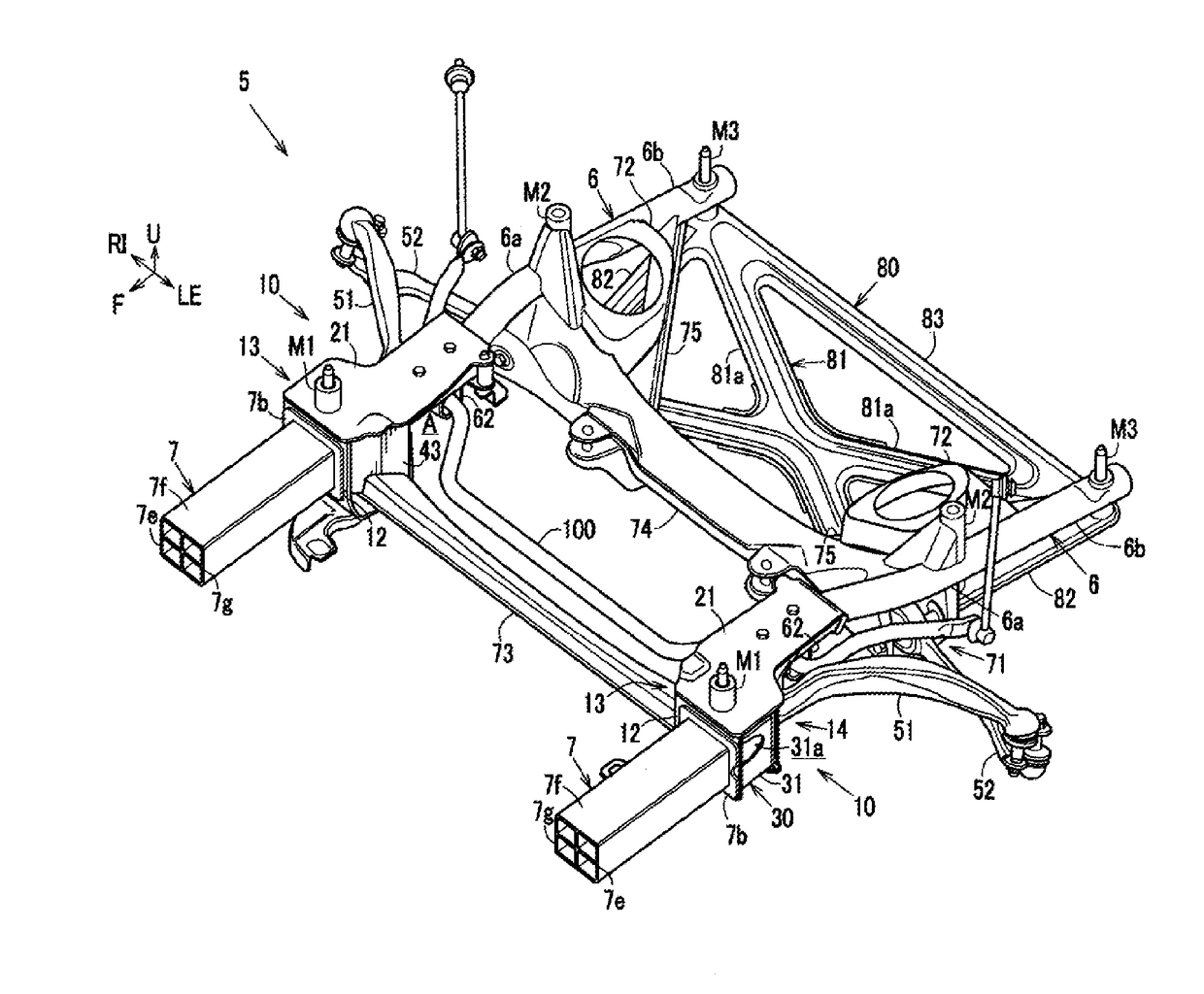
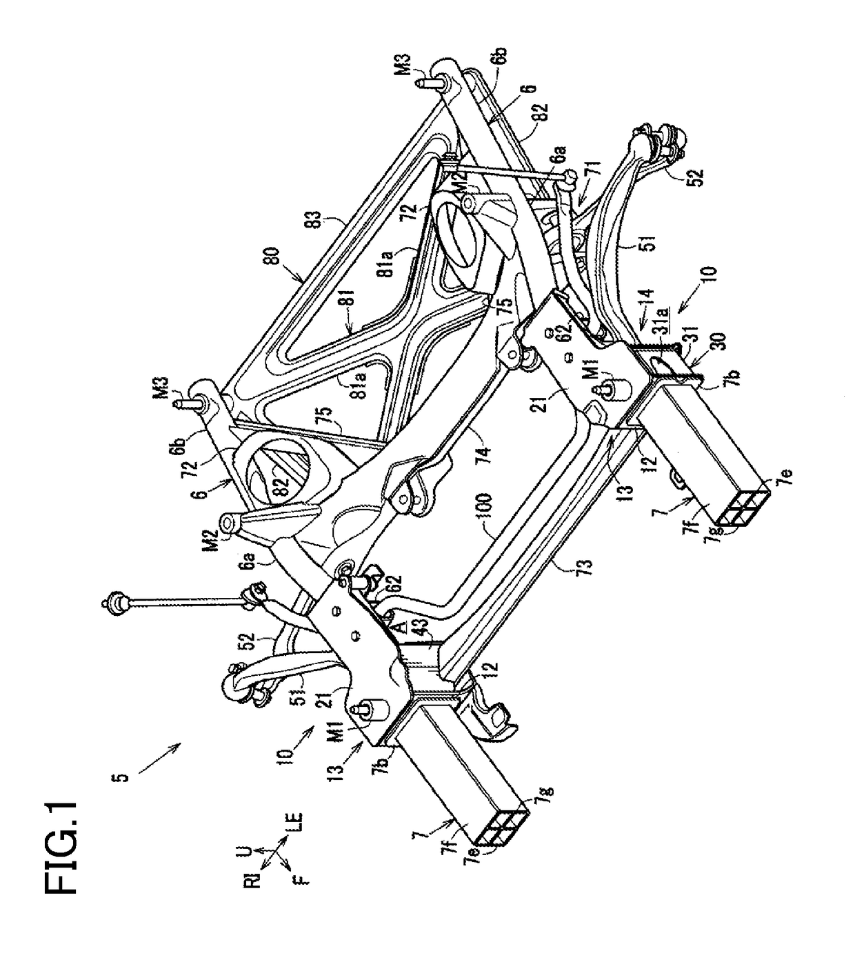
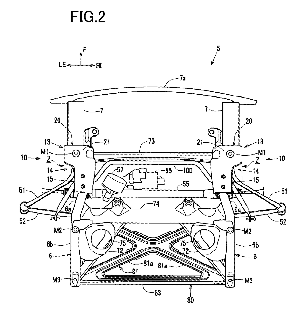
[0030]FIGS. 1 through 7 illustrate a front sub-frame structure of an automobile of this embodiment.
[0031]In particular, FIG. 1 is a perspective view of a front sub-frame of the vehicle according to this embodiment when viewed downward from an obliquely left front portion. FIG. 7 is a disassembled perspective view of a brace and the front sub-frame from which the brace is detached, when viewed from below.
[0032]In the drawings concerning this embodiment except FIG. 2, a steering rack 55, a power steering actuator (a power steering motor) 56, and a power steering pinion 57 are not shown. FIG. 4 does not show tension rods 51 and lower arms 52. FIGS. 5 and 6 do not show a bumper reinforcement 7a. FIGS. 7 and 8 described later do not show a stabilizer support part 62 and a stabilizer 100, in addition to the bumper reinforcement 7a, the tension rods 51, and the lower arms 52. In addition, in the drawings conce...
PUM
 Abstract
Description
Claims
Application Information