Connector, a forming mold therefor

a technology of connecting rods and forming molds, which is applied in the direction of coupling device connections, manufacturing tools, other domestic articles, etc., can solve the problems of narrow molding pins deformation, narrow molding pins that may not have sufficient strength, and insufficient formation of terminal holding holes

Inactive Publication Date: 2009-08-04
SUMITOMO WIRING SYST LTD
View PDF2 Cites 2 Cited by
  • Summary
  • Abstract
  • Description
  • Claims
  • Application Information

AI Technical Summary

Benefits of technology

[0011]The walls of the terminal holding holes conventionally extended out of the holding wall and were continuous over the entire circumference without interruption. Long narrow pins were required for forming the conventional terminal holding holes and necessarily extended from one mold. However, the connector of the subject invention has separated tight holding walls for holding the terminal fittings. The terminal holding holes can be formed by two molds arranged at the inner and outer sides of the holding wall. One mold can be moved until reaching the outer surface of the holding wall. Accordingly, it is sufficient for the parts for forming the terminal holding holes to have a length substantially equal to the thickness of the holding wall. These parts have high strength and are not deformed by an injection pressure during molding. Therefore, the terminal holding holes are formed properly.
[0015]One or more widened recesses preferably are formed at the opening edges of the respective terminal holding holes in the inner surface of the holding wall. The widened recesses preferably are formed in an arranging direction of the tight holding walls. The widened recesses reduce the thickness of the holding wall in parts where the tight holding walls are provided. Therefore, forces necessary to insert the terminal fittings can be reduced.
[0018]As described above, the molding pins have a length substantially equal to the entire length of the terminal holding holes (thickness of the holding wall), and hence are stronger than in the prior art. Thus, the molding pins do not deform even if subjected to the pressure of the resin during the molding. Therefore, the connector can be formed with higher accuracy.
[0020]Accordingly, the terminal holding holes are formed by the contact of the molding pins and the contact plates. Additionally, the tight holding walls projecting from the rear surface of the connector at the opposite sides of the respective terminal holding holes are formed simultaneously from the resin filled between the adjacent contact plates. The tight holding walls formed in this way enable the connector to hold the terminal fittings reliably.
[0021]A base may be formed at the base end of each molding pin and is widened laterally from a shaft of the molding pin towards opposite sides with respect to an arranging direction of the terminal holding holes. Thus, the inner surface of the holding wall has wide recesses adjacent to opposite sides of the terminal holding holes with respect to the arranging direction. The bases are thicker than the shafts and make the molding pins strong. Additionally, base ends of the tight holding walls at opposite sides of the terminal holding holes are thinned because of the recesses at the opening edges of the terminal holding holes. Therefore, there is an additional effect of enabling the terminal holding holes to be widened smoothly for inserting the terminal fittings.

Problems solved by technology

Accordingly, molding pins must be narrower, and the narrow molding pins may not have sufficient strength.
Specifically, there is a possibility that the narrow molding pins will deform when subjected to an injection pressure of resin during molding.
Then, the terminal holding holes might not be formed properly, for example, due to deviation from the specified positions.

Method used


Image

  • Connector, a forming mold therefor
  • Connector, a forming mold therefor
  • Connector, a forming mold therefor

Examples


Embodiment Construction

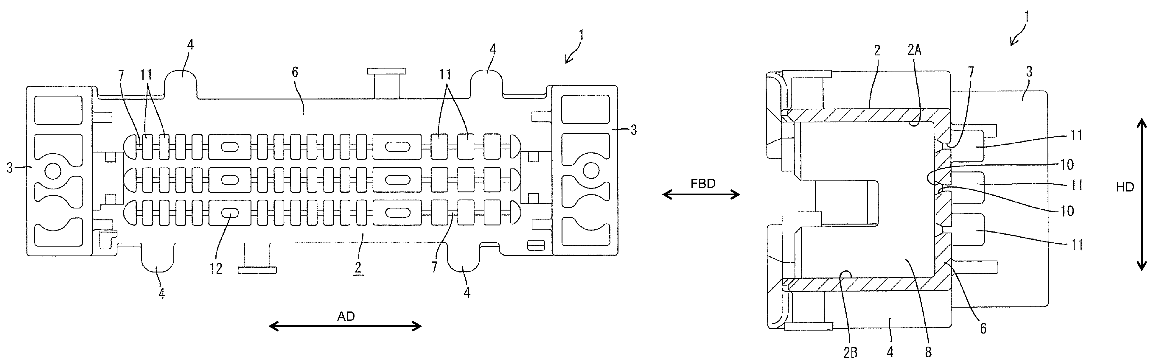
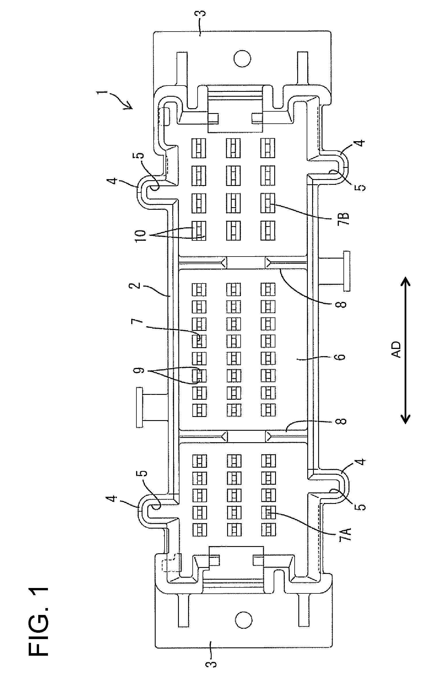
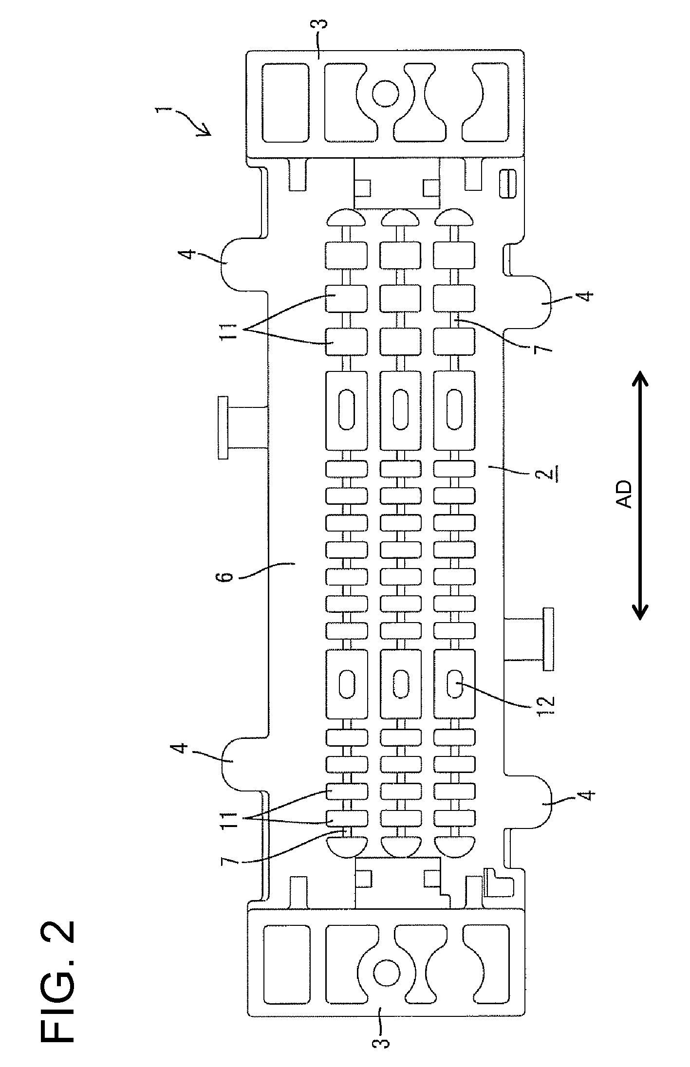
[0029]A circuit board connector in accordance with the invention has a housing identified generally by the numeral 1 in FIGS. 1 to 4 and 6. The housing 1 is formed unitarily of a synthetic resin and includes a main body 2 in the form of a substantially rectangular tube with an open front for receiving a mating connector (not shown). Two bulges 3 are formed at the rear ends of the opposite shorter side surfaces of the main body 2 and are used to mount the housing 1 and two guides 4 project from each of the opposite longer side surfaces of the main body 2. Guide grooves 5 extend back in the respective guides 4 and are engageable with guide ribs (not shown) of a mating housing. Proper engagement of the guide ribs and the guide grooves 5 guide the connection of the two housings and prevent a connection if one of the housings is oriented improperly.

[0030]A holding wall 6 is formed at the back of the main body 2 and functions for holding terminal fittings. Although not shown in detail, th...


PUM

PropertyMeasurementUnit
dimensionaaaaaaaaaa
lengthaaaaaaaaaa
Forcesaaaaaaaaaa

Abstract

A holding wall (6) of a connector housing (1) has terminal holding holes (7) for receiving terminal fittings. Two tight holding walls (11) are formed at opposite sides of each terminal holding hole (7) on the outer surface of the holding wall (6). The terminal fitting is pressed into the terminal holding hole (7) and between the tight holding walls (11). Further, the terminal holding holes (7) are formed by molding pins (14) having a length substantially equal to the thickness of the holding wall (6) and contact plates (13) that contact the leading ends of the molding pins (14). Thus, the molding pins (14) can be short and are less likely to deform when subjected to pressure from resin during molding.

Description

BACKGROUND OF THE INVENTION[0001]1. Field of the Invention[0002]The invention relates to a connector and to a forming mold therefor.[0003]2. Description of the Related Art[0004]Japanese Unexamined Patent Publication No. H06-68927 discloses a connector with a housing that has a terminal holding wall. Terminal holding holes penetrate the terminal holding wall. The connector of Japanese Unexamined Patent Publication No. H06-68927 also has tab-shaped terminal fittings made entirely of narrow metal bars. The terminal fittings are cross-sectionally larger than the terminal holding holes and are held by being pressed into the terminal holding holes.[0005]Forces for holding the terminal fittings in the terminal holding holes are obtained from pressing forces of the walls of the hole. Thus, these connectors require a sufficiently long holding hole for holding the pressed-in terminal fittings. Connectors of this type generally thicken only areas where the terminal holding holes are formed rat...

Claims


Application Information

Patent Timeline
Patent Type & Authority Patents(United States)
IPC IPC(8): H01R13/40
CPCB29C45/2628H01R43/24B29L2031/3406
Inventor FUKAMACHI, MAKOTO
Owner SUMITOMO WIRING SYST LTD
Why Eureka
Try Eureka