Wind-up light-directing slat, method of production, application, and sun protection system

A technology of protection system and light guide plate, applied in the field of sun protection system, can solve the problems of inability to manufacture, reduction of slats and light entering the line of sight, storage, etc.

Active Publication Date: 2015-09-02
于水
View PDF10 Cites 3 Cited by
  • Summary
  • Abstract
  • Description
  • Claims
  • Application Information

AI Technical Summary

Problems solved by technology

The disadvantage is that the slats are rigid and can no longer be wound on cores for further processing
[0006] According to Figure 3 of EP 1 21 508 B1 and Figure 4 The disadvantage of the Fresnel structure is that the slats have to be arranged in an oblique position at an angle of incidence of 45°, which results in a reduced line-of-sight between the slats and the light entry
Another disadvantage is that: in Figure 4 At angles of incidence greater than 45° even at an inclined slat position, a second reflection will occur on the underside of the slat
It can be seen that a further disadvantage is that due to the concentration effect of the reflected radiation, the underside may have a surge of power, which would lead to extreme glare
The disadvantage of such slats is that they cannot be produced from already produced surface-treated strip material, but only as extruded slats with the disadvantage of requiring a subsequent surface treatment
Another disadvantage is that ready-made slats and extruded slats cannot be wound on cores and stored in the premises of subsequent processing plants
The slats can only be processed further if they are cut into sheet-like pieces of the desired length in an expensive manner

Method used


Image

  • Wind-up light-directing slat, method of production, application, and sun protection system
  • Wind-up light-directing slat, method of production, application, and sun protection system
  • Wind-up light-directing slat, method of production, application, and sun protection system

Examples


Embodiment Construction

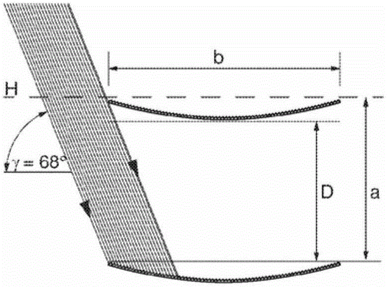
[0065] exist Figure 4 A construction description for the horizontal operating position of the curve is defined in . In the present case, the ratio a / b of the slat distance a to the slat width b is approximately 0.7. However, this ratio can be chosen arbitrarily. For the optional ratio a / b, the solar radiation folding side K in the region of the slat edge will be explained below s Angle of inclination β with respect to the horizontal.

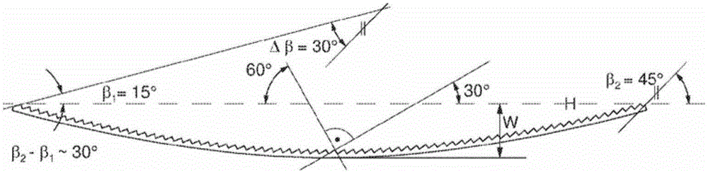
[0066] Valid for horizontal position is α' s =90°-α s . alpha s is the angle of inclination of the shadow line S relative to the vertical line V or relative to the vertical glazing of the building facade to which the sun protection system in which the slats are arranged is applied. For the sun side K in the area of ​​the slat edge relative to the interior space I s Angle of inclination β; the following criteria are valid:

[0067] beta 1 = α s / 2

[0068] beta 2 = α s

[0069] beta 1 is the sun side K relative to the irradiated ...


PUM


Abstract

Light guiding slat for a sun protection system, wherein the light guiding slat is made of a band material equipped with a Fresnel reflector made by folding and / or bending the band material whereby the light guiding slat has a total height (G) which is so small that the light guiding slat has a form to be coilable with a coiling radius of 1 m or less without any substantial plastic deformation.

Description

technical field [0001] The invention relates to a solar protection system made of light guide strips made of tape material and light guide strips with folded structure, wherein at least the upper side of the light reflection strips of the folded structure light guide strips has parallel folded grooves. Under proper operation, the fold has a solar irradiated fold side K s and the folded side K, which is largely shielded. Furthermore, the invention relates to the manufacturing method and the use of the light-guiding slats in solar protection systems. Background technique [0002] It is known to form the slats in a folded shape when the folds are processed by embossing them onto the upper side or to form the slats at least partially with large folds. The disadvantage is that these strips are rigid and can no longer be wound on cores for further processing. These folds will be deformed or the slats will be twisted, unable to elastically return to their straight original posit...

Claims


Application Information

Patent Timeline
Patent Type & Authority Applications(China)
IPC IPC(8): E06B9/386E06B9/24
CPCE06B2009/2417E06B9/386E06B9/264E06B9/24E06B9/40G02B5/09E06B2009/2643G02B2207/123
Inventor 赫尔穆特·克斯特
Owner 于水
Why Eureka
Try Eureka