
Gas tube structure

a technology of gas tube and pipe body, applied in the direction of hose connection, pipe joint, adjustable joint, etc., can solve the problems of increased cost, increased manpower, and easy deformation of pipe body, and achieve the effect of stable connection, no deformation or loosening, and safe us

Active Publication Date: 2014-09-09
CHUNG CHIU CHIH
View PDF6 Cites 3 Cited by
  • Summary
  • Abstract
  • Description
  • Claims
  • Application Information

AI Technical Summary

Benefits of technology

The present invention provides a stable connection between fixed and movable connectors that is safe and will not deform or loosen. The connection is achieved through a sleeve connected to the inner end of the movable connector, which can be rotated by engagement of an engaging groove and a C-shaped buckle. The fixed connector has a buckle ring at the connection section, and the sleeve has a stop flange that prevents the movable connector from rotating at the outer end of the fixed connector. This ensures that the connection is secure and stable, and eliminates the risk of injury or damage due to the use of the present invention.

Problems solved by technology

The C-shaped buckle 35 has a gap, which may be deformed easily and is not strong enough.
The C-shaped buckle 35 may be pulled away by accident, so it is not safe for use.
The fastening ring 20 is welded to the fixed connector 30 to form a weld point A. This way consumes manpower and increases cost.
The weld point is exposed to result in a crack and cannot be used.
This structure is complicated and is difficult to assemble.

Method used


Image

  • Gas tube structure
  • Gas tube structure
  • Gas tube structure

Examples


Embodiment Construction

[0016]Embodiments of the present invention will now be described, by way of example only, with reference to the accompanying drawings.

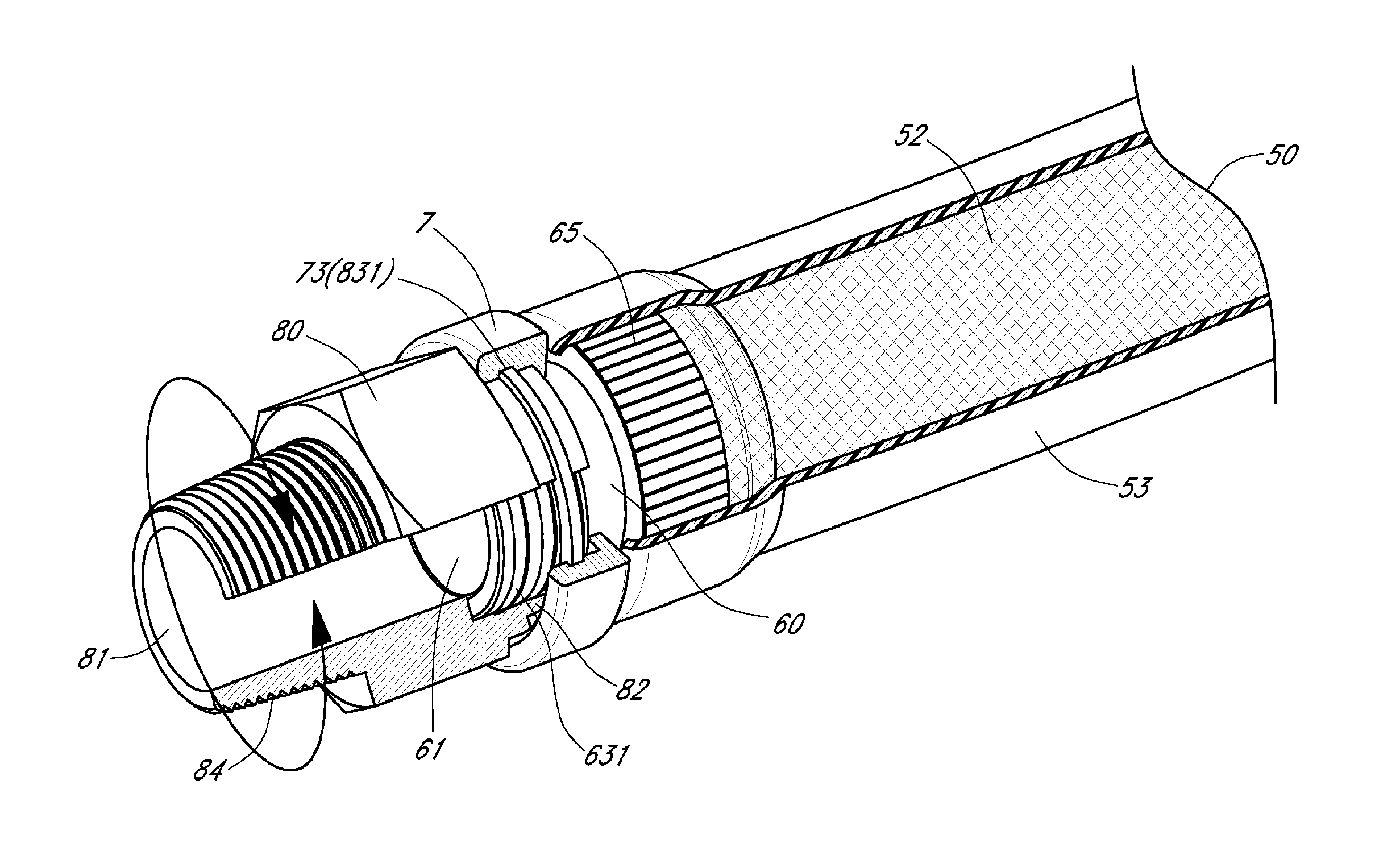
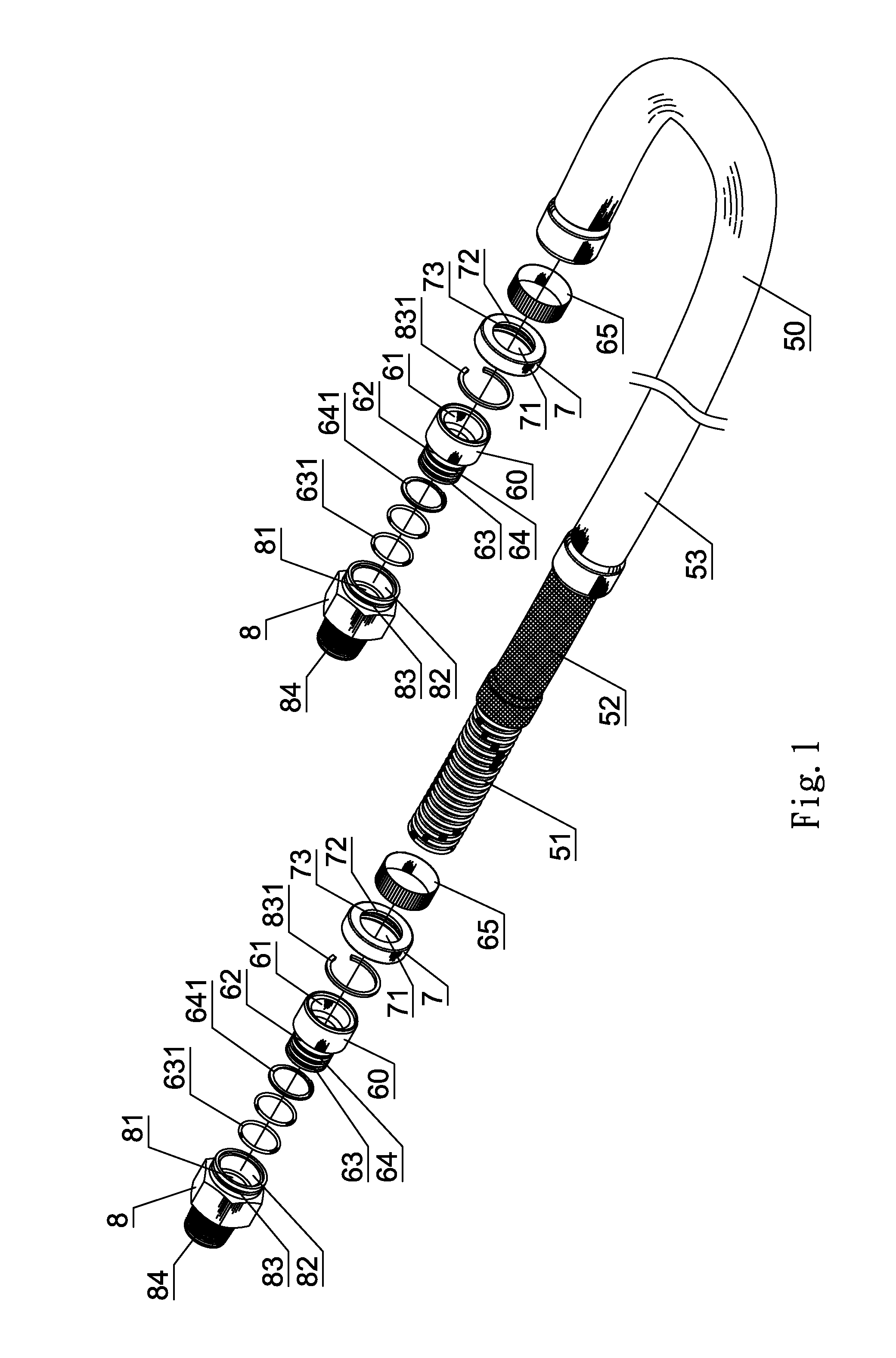
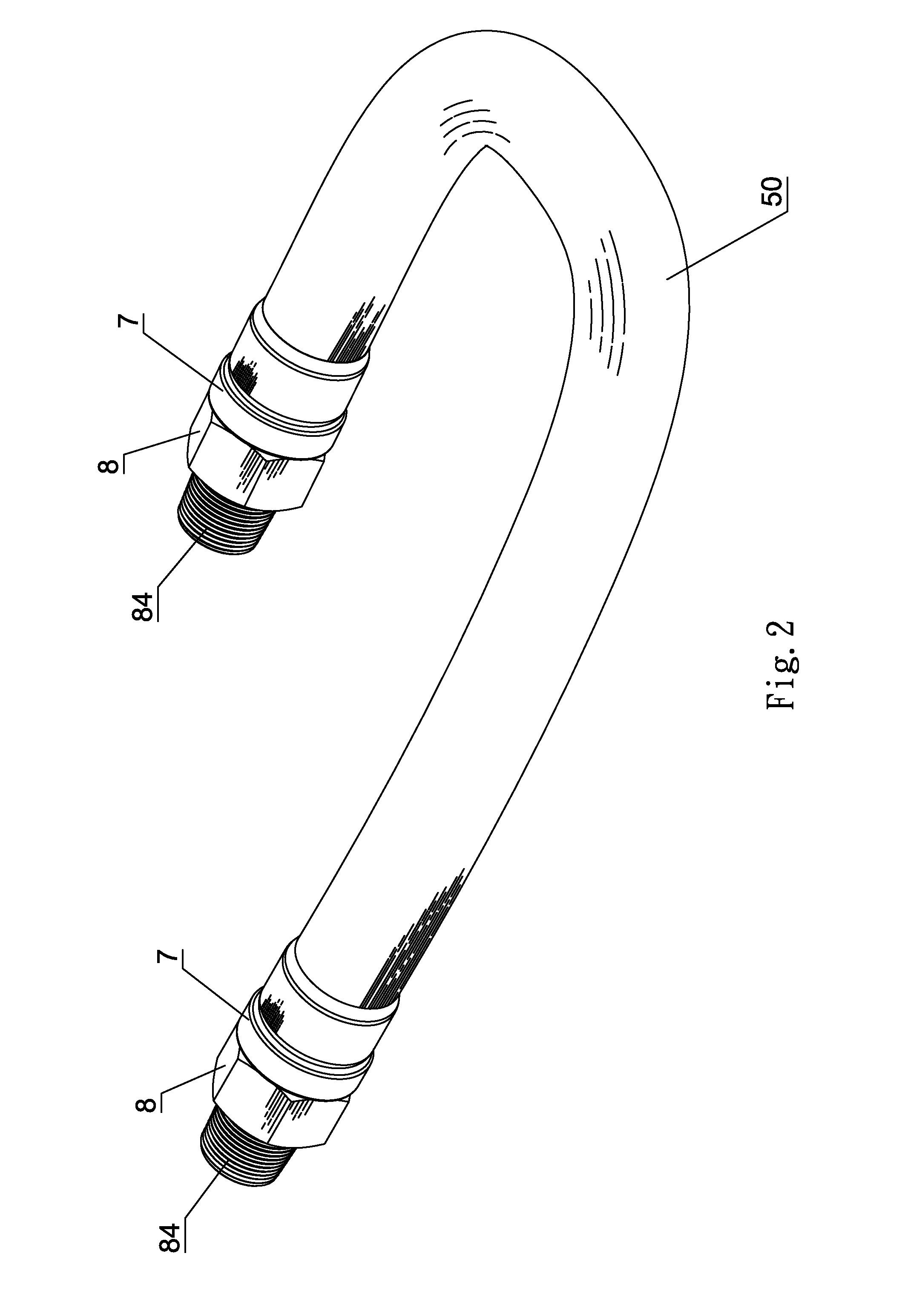
[0017]As shown in FIG. 1 through FIG. 3, the end of a flexible tube 50 is connected with a fixed connector 60. A sleeve 7 is fitted on the fixed connector 60. The fixed connector 60 and the sleeve 7 are connected to a movable connector 80. The flexible tube 50 includes a metallic tube layer 51, a metallic net layer 52 and a plastic tube layer 53 which are stacked from inside to outside in sequence. The fixed connector 60 is made of metal. The fixed connector 60 has a central through hole 61. The inner end of the fixed connector 60 is welded to the end of the metallic tube layer 51 to form a weld point A. A fastening ring 65 is connected with the metallic net layer 52 and fitted on the inner end of the fixed connector 60. The plastic tube layer 53 covers the fastening ring 65 to be one-piece. The fixed connector 60 has a connection section 62 extending...


PUM


Abstract

A gas tube structure includes a flexible tube. The end of the flexible tube is connected with a fixed connector. A sleeve is fitted on the fixed connector. The fixed connector and the sleeve are connected to a movable connector. The fixed connector has a connection section extending from an outer end thereof. The connection section has an annular seal groove and an annular buckle groove thereon. The sleeve has a sleeve hole therein, a stop flange at one end thereof and an engaging groove formed on in inner wall thereof. One end of the movable connector has a receiving hole and a C-shaped groove formed on an outer wall of the receiving hole. The C-shaped groove is adapted to receive a C-shaped buckle. The present invention has a stable connection, is safe for use, can lower the cost and enhances assembly efficiency.

Description

BACKGROUND OF THE INVENTION[0001]1. Field of the Invention[0002]The present invention relates to a gas tube structure, and more particularly to a gas tube for connection of a metallic gas tube, a gas barrel, a gas stove or a water heater. The gas tube is used to connect the metallic gas tube / gas barrel and the gas stove / water heater.[0003]2. Description of the Prior Art[0004]A soft gas tube is used to connect a metallic gas tube / gas barrel and a gas stove / water heater. For lock, the end of soft gas tube is rotatable. In U.S. Pat. No. 5,553,893 as shown in FIG. 5, the end of a flexible tube 10 is provided with a fastening ring 20. The fastening ring 20 is connected with a fixed connector 30. The fixed connector 30 is connected with a movable connector 40. The flexible tube 10 includes a metallic tube layer 11, a metallic net layer 12 and a plastic tube layer 13 which are stacked from inside to outside in sequence. The fastening ring 20 is made of metal. The fixed connector 30 is made...

Claims


Application Information

Patent Timeline
Patent Type & Authority Patents(United States)
IPC IPC(8): F16L27/08
CPCF16L33/01F16L33/26F16L27/0816
Inventor CHUNG, CHIU-CHIH
Owner CHUNG CHIU CHIH
Learn More