Portable apparatus component fixation structure

Inactive Publication Date: 2018-09-13
SEIKO INSTR INC
View PDF10 Cites 1 Cited by
  • Summary
  • Abstract
  • Description
  • Claims
  • Application Information

AI Technical Summary

Benefits of technology

[0027]In this construction, it is possible to mount the display plate of the timepiece to the main plate in a state in which the positioning accuracy is secured. Further, it is possible to mount the displa

Problems solved by technology

If, however, the protruding dimension of the columnar protrusions were increased, the thickness of th

Method used


Image

  • Portable apparatus component fixation structure
  • Portable apparatus component fixation structure
  • Portable apparatus component fixation structure

Examples


first embodiment

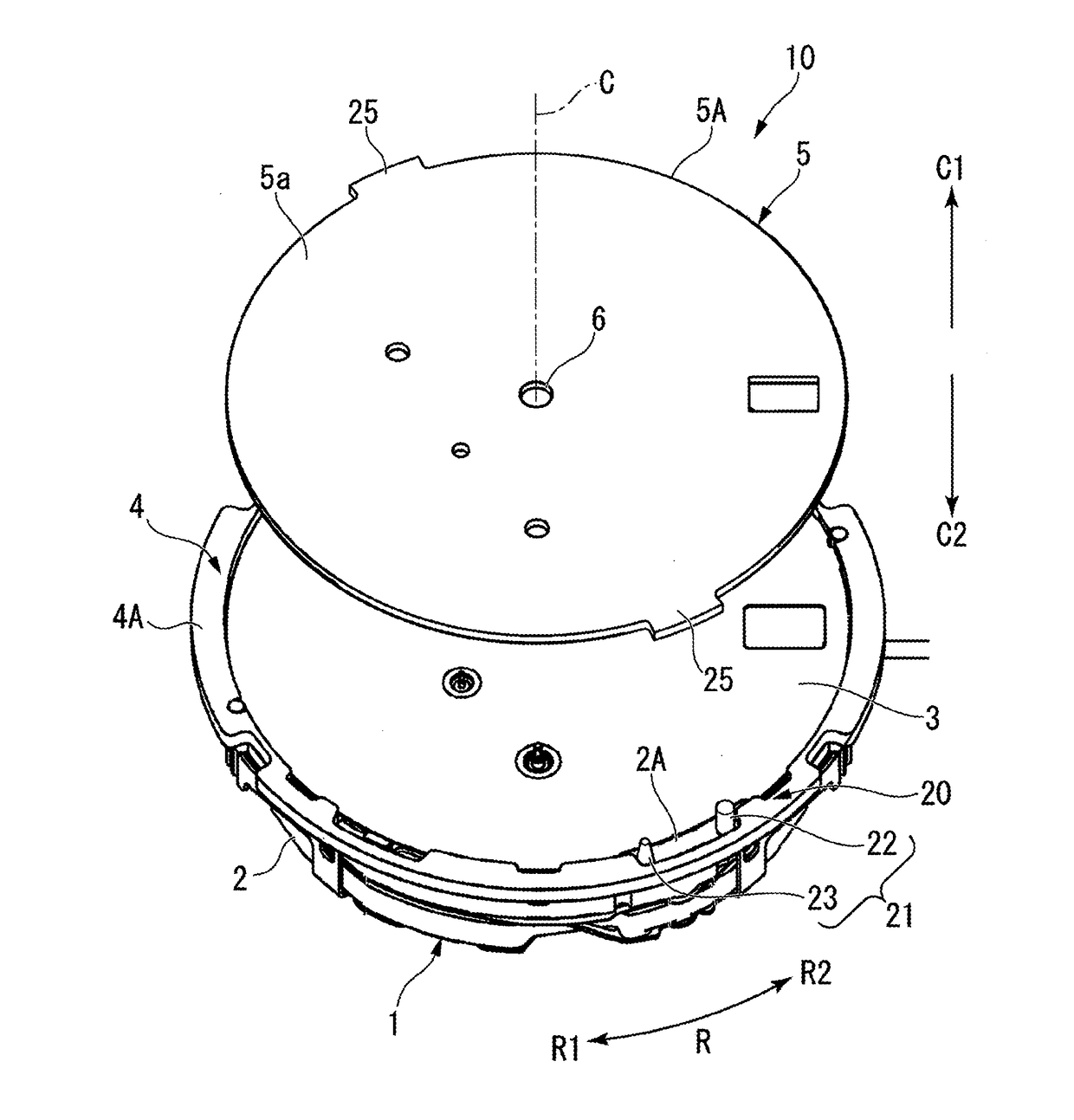
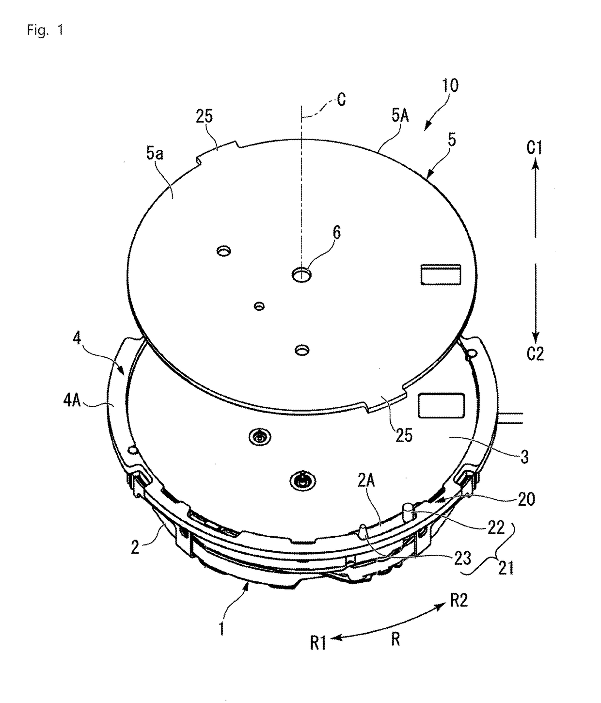
[0042]FIG. 1 is an exploded perspective view of a timepiece 10 according to the first embodiment.

[0043]As shown in FIG. 1, the timepiece 10 is equipped with a movement 1 and a display plate 5. The movement 1 is equipped with a main plate 2, a solar battery 3, a frame body 4, and an indicator hand shaft (not shown). The display plate 5 is a second member, and the main plate 2 is a first member.

[0044]Symbol C indicates a center axis of the timepiece 10. Of the directions along the center axis C, one direction is referred to as a first axial direction C1, and the direction opposite the first axial direction C1 is referred to as a second axial direction C2. The center axis C extends through the center of the movement 1 (the main plate 2, the solar battery 3, the frame body 4, and the indicator hand shaft), and the center of the display plate 5. The directions around the center axis C are referred to as peripheral directions R. Of the peripheral directions R, one direction is referred to...

second embodiment

[0078]FIG. 4 is a plan view of the fixation structure 40 according to the second embodiment. FIG. 5 is a side view of the fixation structure 40 according to the second embodiment.

[0079]As shown in FIGS. 4 and 5, in the fixation structure 40, the regulating portion 25 of the first embodiment is replaced by a regulating portion 42. Otherwise, it is of the same construction as the fixation structure 20 of the first embodiment.

[0080]In the regulating portion 42, the second side 25b of the regulating portion 25 of the first embodiment is replaced by a second side 42a. Otherwise, it is of the same construction as the regulating portion 25 of the first embodiment.

[0081]The second side 42a of the regulating portion 42 is an inclined side opposite the inclined surface 23a of the second pin 23. The second side 42a of the regulating portion 42 is formed in an inclined configuration along the inclined surface 23a of the second pin 23. Thus, the entire second side 42a comes into contact with the...

third embodiment

[0082]FIG. 6 is a plan view of the fixation structure 50 according to the third embodiment. FIG. 7 is a side view of the fixation structure 50 according to the third embodiment.

[0083]As shown in FIGS. 6 and 7, in the fixation structure 50, the second pin 23 of the first embodiment is replaced by a second pin 52. Otherwise, it is of the same construction as the fixation structure 20 of the first embodiment.

[0084]The second pin 52 is formed so as to be gradually increased in diameter from the main plate 2 toward the display plate 5 (in the first axial direction C1). That is, an inclined surface 52a of the second pin 52 is formed so as to be gradually spaced away from an axis 53 as it extends in the first axial direction C1 from the main plate 2. The inclined surface 52a forms the outer peripheral surface of the second pin 52.

[0085]The second pin 52 is mounted to the main plate 2 from the display plate 5 side as indicated by an arrow F3. Examples of the means for mounting the second pi...


PUM


Abstract

A portable apparatus component fixation structure which helps to secure the positioning accuracy for a second member (a mounted member) and which makes it possible to easily mount the second member is to be provided. A fixation structure is equipped with a fixation portion provided on a main plate and a regulating portion formed on a display plate. The fixation portion has a first pin and a second pin. The second pin has an inclined surface. The inclined surface is a surface generating a pressing force toward the regulating portion as the display plate approaches the main plate. Locking is effected in a state in which the regulating portion is held between the first pin and the second pin.

Description

RELATED APPLICATIONS[0001]This application claims priority under 35 U.S.C. § 119 to Japanese Patent Application No. 2017-047481 filed on Mar. 13, 2017, the entire content of which is hereby incorporated by reference.BACKGROUND OF THE INVENTION1. Field of the Invention[0002]The present invention relates to a portable apparatus component fixation structure.2. Description of the Related Art[0003]As a timepiece display plate fixation structure, there has been known one in which a cutout is formed in an outer peripheral portion of a timepiece display plate and in which a pair of columnar protrusions are mounted to an auxiliary ring (hereinafter referred to as a main plate), with the timepiece display plate being mounted to the main plate through engagement of the cutout with the pair of columnar protrusions.[0004]More specifically, the cutout is matched with the pair of columnar protrusions, and, in this state, the timepiece display plate is pressed against the main plate. Due to a wall ...

Claims


Application Information

Patent Timeline
IPC IPC(8): G04D1/00G04D1/10
CPCG04D1/0042G04D1/10G04B19/14
Inventor IGUCHI, KATSUNOBUHATTORI, RYOHARA, YASUNORI
Owner SEIKO INSTR INC
Why Eureka
Try Eureka