Substrate processing apparatus, substrate processing system, and substrate processing method

a substrate processing and substrate technology, applied in the direction of spraying apparatus, spray nozzles, electric devices, etc., can solve the problems of reducing the oxygen concentration in the space between the lid member and the upper limit of the oxygen concentration, affecting the efficiency of cleaning liquid, so as to suppress the effect of reducing the entry of outside air and suppressing the reduction of productivity

Active Publication Date: 2018-09-13
DAINIPPON SCREEN MTG CO LTD
View PDF7 Cites 3 Cited by
  • Summary
  • Abstract
  • Description
  • Claims
  • Application Information

AI Technical Summary

Benefits of technology

[0010]The present invention is intended for a substrate processing apparatus for processing a substrate, and it is an object of the present invention to suppress mixture of a plurality of types of processing liquids. Another object of the present invention is to reduce the entry of outside air into the space between an opposing member and a substrate. Yet another object of the present invention is to hold the opposing member with a simple configuration and to move an opposing-member holder between a holding position and a retracted position with a simple configuration. Yet another object of the present invention is to enable replacement of opposing members to be used and to suppress a reduction in productivity during substrate processing. The present invention is also directed to a substrate processing system for processing a substrate and a substrate processing method of processing a substrate.
[0013]A substrate processing apparatus according to another aspect of the present invention includes a substrate holder for holding a substrate in a horizontal position, an opposing member that opposes an upper surface of the substrate, has an opposing-member opening in a central part, and has a tubular to-be-held part that protrudes upward from the periphery of the opposing-member opening, an opposing-member conveying mechanism for holding the to-be-held part of the opposing member and moving the opposing member relative to the substrate holder between a first position and a second position in an up-down direction, a processing liquid nozzle located on the inner side of the to-be-held part and for ejecting a processing liquid through the opposing-member opening toward the upper surface of the substrate, a substrate rotation mechanism for rotating the substrate along with the substrate holder about a central axis pointing in the up-down direction, and a gas supply part for supplying a gas to a space between the opposing member and the substrate. The opposing member that is located at the first position is held by the opposing-member conveying mechanism and spaced above from the substrate holder, and the opposing member that is located at the second position is held by the substrate holder and rotated along with the substrate holder by the substrate rotation mechanism, and the gas supply part supplies a gas to a gap between an inner surface of the to-be-held part of the opposing member and an outer surface of the processing liquid nozzle. This reduces the entry of outside air into the space between the opposing member and the substrate.
[0015]A substrate processing apparatus according to another aspect of the present invention includes a substrate holder for holding a substrate in a horizontal position, an opposing member that opposes an upper surface of the substrate, has an opposing-member opening in a central part, and has a tubular to-be-held part that protrudes upward from the periphery of the opposing-member opening, an opposing-member holder for holding the to-be-held part of the opposing member, an opposing-member elevating mechanism for moving the opposing member relative to the substrate holder between a first position and a second position in an up-down direction, a processing liquid nozzle located on the inner side of the to-be-held part and for ejecting a processing liquid through the opposing-member opening toward the upper surface of the substrate, a substrate rotation mechanism for rotating the substrate along with the substrate holder about a central axis pointing in the up-down direction, and an opposing-member-holder moving mechanism for moving the opposing-member holder between a holding position above the opposing member and a retracted position around the opposing member. The opposing member that is located at the first position is held by the opposing-member holder and spaced above from the substrate holder, and the opposing member that is located at the second position is held by the substrate holder and rotated along with the substrate holder by the substrate rotation mechanism. The to-be-held part includes a cylindrical flange connector centered on the central axis, and an opposing-member flange part that extends radially outward from an upper end of the flange connector. The opposing-member holder includes: a first flange supporter that is in contact with and supports part of the opposing-member flange part of the opposing member from the underside when the opposing member is located at the first position, a second flange supporter that is located on the opposite side to the first flange supporter with the flange connector located therebetween and that is in contact with and supports part of the opposing-member flange part of the opposing member from the underside when the opposing member is located at the first position, and a holder body on which the first flange supporter and the second flange supporter are mounted. With the opposing member being located at the second position, the first flange supporter and the second flange supporter are horizontally moved to space the first flange supporter and the second flange supporter radially outward from the opposing-member flange part or to dispose the first flange supporter and the second flange supporter below the opposing-member flange part. This configuration allows the opposing member to be held with a simple configuration and allows the opposing-member holder to move between the holding position and the retracted position with a simple configuration.
[0017]A substrate processing apparatus according to another aspect of the present invention includes a substrate holder for holding a substrate in a horizontal position, an opposing member that opposes an upper surface of the substrate, a processing liquid supply part for supplying a processing liquid to the upper surface of the substrate, a substrate rotation mechanism for rotating the substrate along with the substrate holder about a central axis pointing in an up-down direction, an opposing-member storage part capable of housing the opposing member, and an opposing-member conveying mechanism for holding the opposing member, moving the opposing member relative to the substrate holder between a first position and a second position in the up-down direction, and conveying the opposing member between a position above the substrate holder and the opposing-member storage part. The opposing member that is located at the first position is held by the opposing-member conveying mechanism and spaced above from the substrate holder, and the opposing member that is located at the second position is held by the substrate holder and rotated along with the substrate holder by the substrate rotation mechanism, and the opposing-member conveying mechanism conveys the opposing member from the position above the substrate holder into the opposing-member storage part and conveys another opposing member housed in the opposing-member storage part out of the opposing-member storage part to the position above the substrate holder. This configuration enables replacement of opposing members to be used.

Problems solved by technology

This may cause mixture of the cleaning liquid and deionized water in the nozzle.
Thus, there is an upper limit to the extent of a reduction in the oxygen concentration in the space between the lid member and the wafer.
This may complicate a configuration for holding the lid member.
As a result, residues of the cleaning liquid may be gradually accumulated on the lower surface of the lid member and become a source of pollution.
At this time, the substrate cleaning apparatus is unable to perform processing such as cleaning the substrate, and therefore, the productivity of the apparatus may be reduced.

Method used


Image

  • Substrate processing apparatus, substrate processing system, and substrate processing method
  • Substrate processing apparatus, substrate processing system, and substrate processing method
  • Substrate processing apparatus, substrate processing system, and substrate processing method

Examples


first embodiment

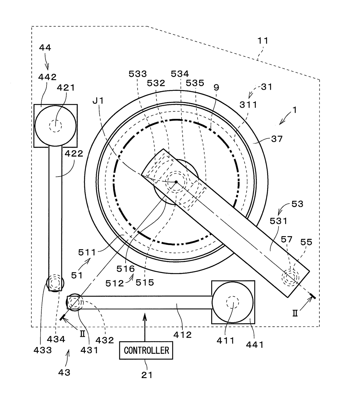
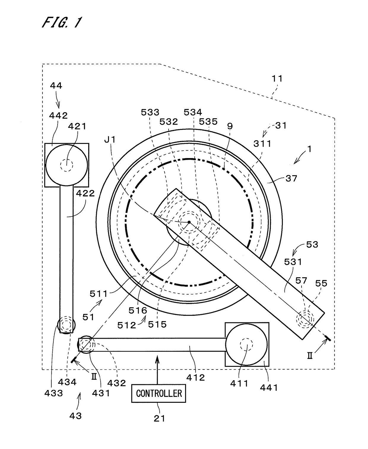
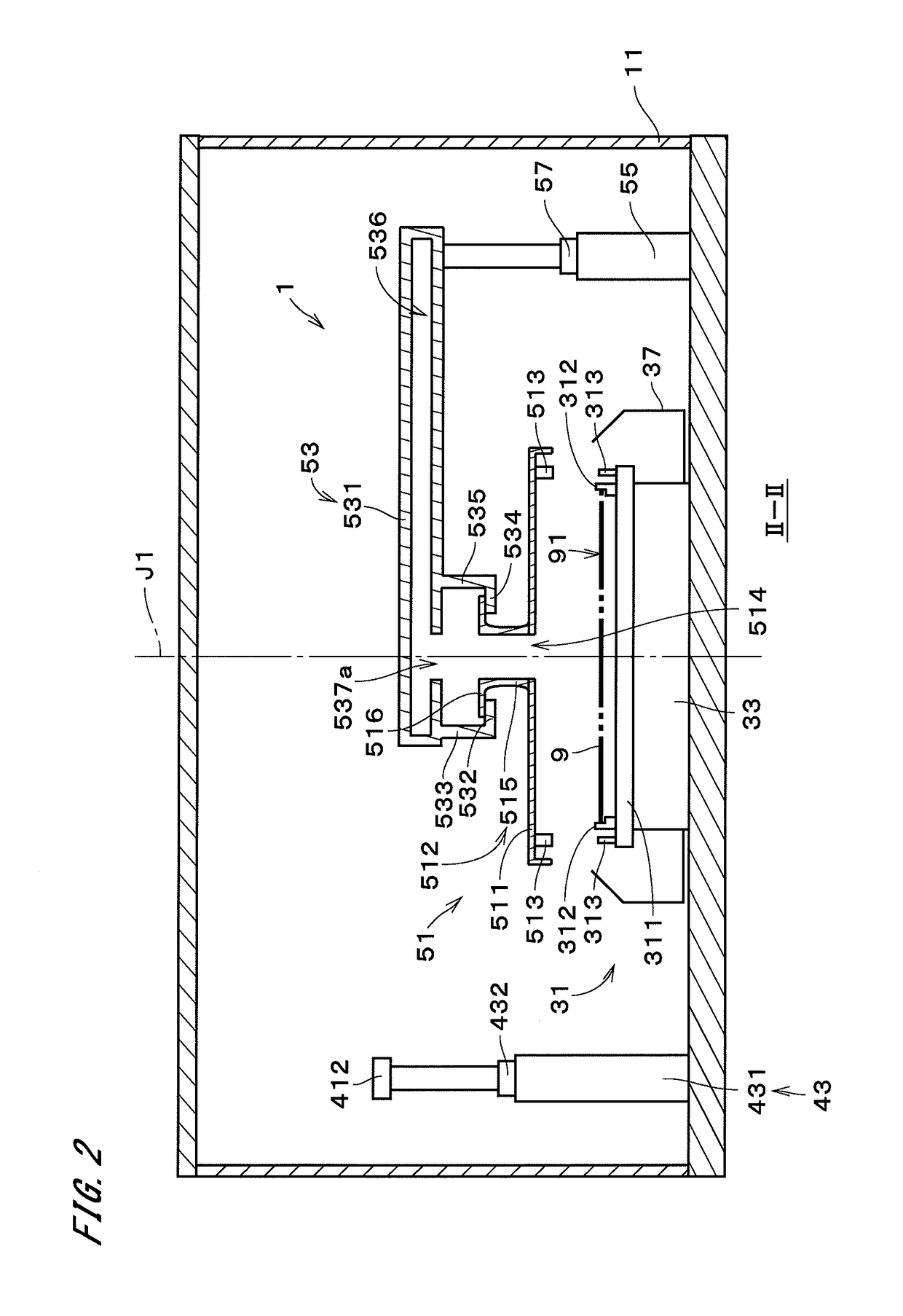
[0068]FIG. 1 is a plan view of a substrate processing apparatus 1 according to the present invention. FIG. 2 is a cross-sectional view of the substrate processing apparatus 1 taken along II-II in FIG. 1. The substrate processing apparatus 1 is a sheet-fed apparatus for processing semiconductor substrates 9 (hereinafter, simply referred to as “substrates 9”) one at a time. The substrate processing apparatus 1 is housed in a housing 11, which is an apparatus housing chamber. In FIG. 1, the housing 11 is indicated by a broken line.

[0069]The substrate processing apparatus 1 includes a controller 21, a substrate holder 31, a substrate rotation mechanism 33, a cup part 37, a first processing liquid nozzle 411, a second processing liquid nozzle 421, a nozzle moving mechanism 43, a nozzle cleaning part 44, a top plate 51, an opposing-member holder 53, an opposing-member elevating mechanism 55, and an opposing-member-holder moving mechanism 57. The controller 21 controls constituent elements...

second embodiment

[0143]FIG. 13 is a plan view of a substrate processing apparatus 1a according to the present invention. The substrate processing apparatus 1a includes, instead of the opposing-member holder 53, an opposing-member holder 53a that differs in the orientations of the first flange supporter 532 and the second flange supporter 534 from the opposing-member holder 53 illustrated in FIGS. 1 and 2. The opposing-member holder 53a also includes a supporter moving mechanism 530. The other configuration of the substrate processing apparatus 1a is similar to the configuration of the substrate processing apparatus 1 illustrated in FIG. 1, and constituent elements that correspond to those of the substrate processing apparatus 1 are given the same reference numerals in the following description.

[0144]As illustrated in FIG. 13, the first flange supporter 532, the first connector 533, the second flange supporter 534, and the second connector 535 of the opposing-member holder 53a are mounted on the end ...

third embodiment

[0152]FIG. 15 is a plan view of a substrate processing apparatus 1b according to the present invention. FIG. 16 is a cross-sectional view of the substrate processing apparatus 1b taken along XVI-XVI in FIG. 15. An opposing-member holder 53b of the substrate processing apparatus 1b includes a flange supporter 538 and a connector 539, instead of the first flange supporter 532, the first connector 533, the second flange supporter 534, and the second connector 535 of the substrate processing apparatus 1. The substrate processing apparatus 1b also includes a first processing liquid nozzle 411a and a second processing liquid nozzle 421a that have different configurations from the configurations of the first processing liquid nozzle 411 and the second processing liquid nozzle 421. In the substrate processing apparatus 1b, the opposing-member-holder moving mechanism 57 illustrated in FIG. 1 is omitted, and the first processing liquid nozzle 411a and the second processing liquid nozzle 421a ...


PUM


Abstract

A top plate when located at a first position is held by an opposing-member holder, and the top plate when located at a second position is held by a substrate holder and rotated along with the substrate holder. In a substrate processing apparatus, a first processing liquid nozzle located at a supply position inside a to-be-held part of the top plate supplies a first processing liquid through an opposing-member opening to a substrate and is moved from the supply position to its retracted position, and a second processing liquid nozzle is moved from its retracted position to the supply position and supplies a second processing liquid through the opposing-member opening to the substrate. This configuration suppresses or prevents mixture of multiple types of processing liquids, as compared with the case where multiple types of processing liquids are sequentially supplied from a single processing liquid nozzle.

Description

CROSS-REFERENCE TO RELATED APPLICATIONS[0001]The present application is a divisional of U.S. patent application Ser. No. 15 / 016,411 filed Feb. 5, 2016, which claims priority of Japanese Patent Application Nos. 2015-025718, filed Feb. 12, 2015, 2015-025719, filed Feb. 12, 2015, 2015-025720, filed Feb. 12, 2015 and 2015-037749, filed Feb. 27, 2015, the contents of which are incorporated by reference herein.TECHNICAL FIELD[0002]The present invention relates to a technique for processing a substrate.BACKGROUND ART[0003]A manufacturing process for manufacturing semiconductor substrates (hereinafter, simply referred to as “substrates”) conventionally involves various types of processing to be performed on the substrates. Examples of the processing include chemical processing such as processing for supplying a chemical solution onto a substrate that has a resist pattern on its surface to etch the surface of the substrate. The chemical processing is followed by cleaning processing for clean...

Claims


Application Information

Patent Timeline
Patent Type & Authority Applications(United States)
IPC IPC(8): H01L21/67
CPCH01L21/67051H01L21/6715B05B13/04B05B1/14B05B12/16
Inventor MURAMOTO, RYOTAKAHASHI, MITSUKAZU
Owner DAINIPPON SCREEN MTG CO LTD
Why Eureka
Try Eureka