Transmission device, transmission method, reception device, and reception method

a technology of transmission device and reception device, applied in the field of transmission device, transmission method, reception device, reception method, etc., to achieve the effect of preventing the disturbance of imag

Active Publication Date: 2018-09-13
SONY CORP
View PDF4 Cites 4 Cited by
  • Summary
  • Abstract
  • Description
  • Claims
  • Application Information

AI Technical Summary

Benefits of technology

[0025]According to an embodiment of the present technology, it is possible to satisfactorily prevent an image disturbance from occurring at a reception side when a plurality of mixed types of transmission video data having different dynamic ranges are transmitted. Note that effects described in the present specification are merely illustrative and are not limitative, and additional effects may be exhibited.

Problems solved by technology

When such switching occurs, it is necessary for a reception side to switch electro-optical transfer characteristics; however, an image disturbance occurs resulting from the switching, or display muting is performed to hide the image disturbance.

Method used


Image

  • Transmission device, transmission method, reception device, and reception method
  • Transmission device, transmission method, reception device, and reception method
  • Transmission device, transmission method, reception device, and reception method

Examples


embodiment

1. Embodiment

Configuration Example of a Transmission and Reception System

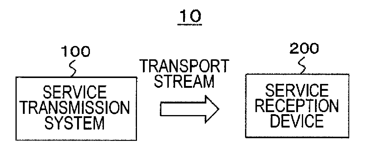
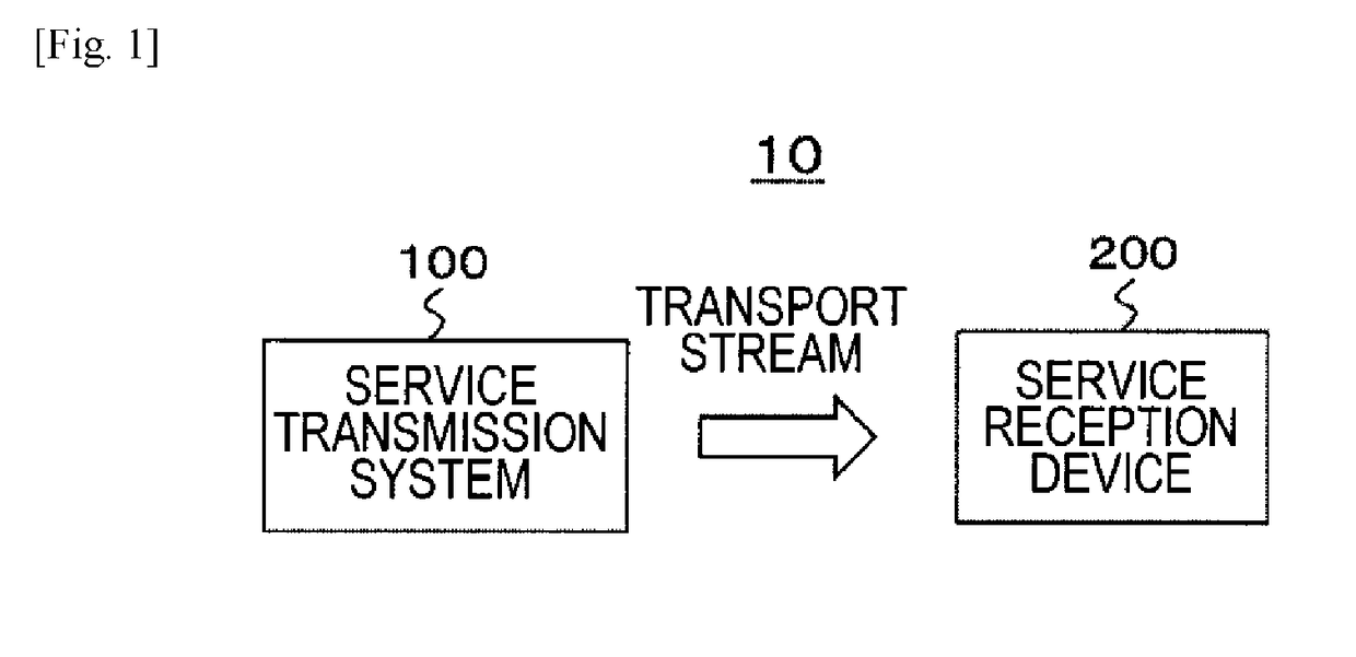
[0046]FIG. 1 shows a configuration example of a transmission and reception system 10 as an embodiment. The transmission and reception system 10 is constituted by a service transmission system 100 and a service reception device 200. The service transmission system 100 generates an MPEG-2 transport stream (TS) or a transport stream of MPEG media transport (MMT) (multiplexed stream) as a container, and puts the transport stream on a broadcasting wave or packets of a network to transmit the transport stream.

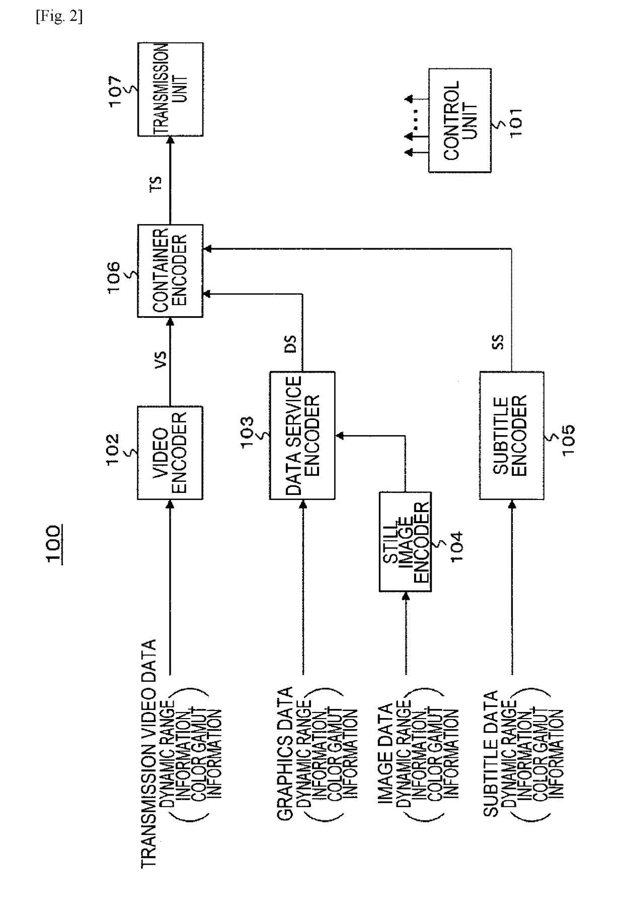
[0047]The transport stream includes a first component stream (a video stream) having transmission video data obtained by switching between a plurality of types of transmission video data as component data and a predetermined number of second component streams having other component data. The predetermined number of second component streams include, for example, a data service stream (a data broadcasting stream) ...


PUM


Abstract

There is provided a transmission device including: a transmission unit that transmits a container in a predetermined format including a first component stream that has, as component data, transmission video data obtained by switching between a plurality of types of transmission video data, and a predetermined number of second component streams that have pieces of other component data; and an information insertion unit that inserts dynamic range information of the component data that each of the component streams has into the component streams.

Description

CROSS REFERENCE TO RELATED APPLICATIONS[0001]This application claims the benefit of Japanese Priority Patent Application JP 2015-208445 filed Oct. 22, 2015, the entire contents of which are incorporated herein by reference.TECHNICAL FIELD[0002]The present technology relates to a transmission device, a transmission method, a reception device, and a reception method, and particularly to a transmission device and the like for transmitting not only video streams but also other streams having graphics data, subtitle data, and the like.BACKGROUND ART[0003]There are cases in which standard dynamic range transmission video data and high dynamic range transmission video data are mixed and transmitted. Hereinafter, standard dynamic range will be referred to as “SDR” and high dynamic range will be referred to as “HDR” appropriately. In this case, the SDR transmission video data is data obtained by applying an SDR opto-electrical transfer to SDR video data, and the HDR transmission video data i...

Claims


Application Information

Patent Timeline
Patent Type & Authority Applications(United States)
IPC IPC(8): H04N21/84H04N21/235H04N21/236
CPCH04N21/84H04N21/235H04N21/236H04N21/23614H04N21/2365H04N21/4318H04N21/4347H04N21/4348H04N21/435H04N21/2362G06T5/007
Inventor TSUKAGOSHI, IKUO
Owner SONY CORP
Why Eureka
Try Eureka