Method for automatic adjustment of the travel of a stretching rod of a device for forming hollow bodies
Active Publication Date: 2018-09-20
SIDEL PARTICIPATIONS SAS
View PDF0 Cites 0 Cited by
Summary
Abstract
Description
Claims
Application Information
AI Technical Summary
This helps you quickly interpret patents by identifying the three key elements:
Problems solved by technology
Method used
Benefits of technology
Benefits of technology
[0017]Such a method makes it possible in particular to correct automatically the travel of the stretching rod without having to stop the production of hollow bodies. Actually, the object of said detection is to know whether the axial force at the time when the stretching rod reaches the programmed stretching end position for the stretching of a hollow body is above a determined upper boundary. Said de
Problems solved by technology
Furthermore, such a forming device is very expensive.
However, it may happen that the operator makes an error or else that the thickness of the bottom wall of the preforms and/or the dimensions of the molds are not in compliance with the specifications.
In this case, it may happen that the stretching rod abuts against the mold bottom and/or that it forces the preform wall too heavily against the mold bottom.
When the axial force that is detected is too high, it is c
Method used
Image
Click on the blue label to locate the original text in one second.
Reading with bidirectional positioning of images and text.
Examples
Example
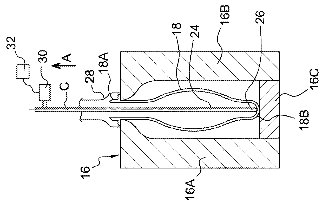
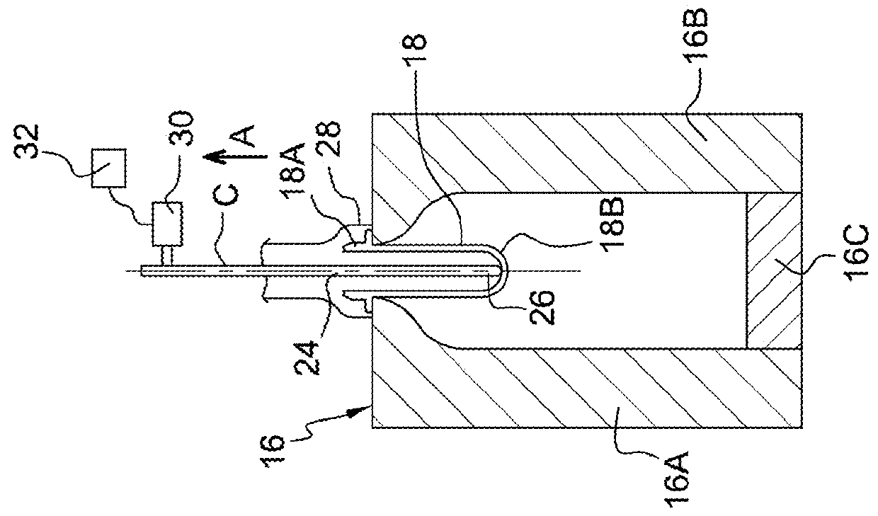
[0064]According to a first embodiment of the invention that is shown in FIG. 4, the method for adjusting the travel of the sliding rod 24 comprises a first step “E1” for detecting the axial force that opposes the sliding of the stretching rod 24 at the end of travel, i.e., close to its stretching end position.
[0065]During a second verification step “E2,” the axial force that is detected during the first step “E1” is compared to an upper boundary.
[0066]If the detected axial force is below the upper boundary, it is considered that the stretching end position is correctly adjusted. The adjustment method is then repeated without modification of the initial stretching end position.
[0067]If the axial force that is detected is above the upper boundary, it is considered that the stretching end position is not correctly adjusted. The travel of the stretching rod 24 is then considered as being too long.
[0068]When the axial force that is detected exceeds the upper boundary during at least one ...
Example
[0076]A second embodiment of the invention was shown in FIG. 5.
[0077]This second embodiment proposes quickly approaching a suitable stretching end position while decreasing the amount of hollow body to be scrapped during the adjustment.
[0078]In this second embodiment, if, for at least one cycle following a third correction step “E3,” the axial force that opposes the sliding of the stretching rod 24 at the end of travel is below a determined lower boundary, a step for adapting the travel of the stretching rod 24 is initiated during which the stretching end position is offset beyond the stretching end position, i.e., downward with reference to FIG. 3, from a determined second distance “d2” that is less than the determined first distance “d1.”
[0079]Thus, the adjustment method comprises the same three steps “E1,”“E2,” and “E3” that are described in the first embodiment of the invention.
[0080]However, at the end of the second verification step “E2,” if the detected axial force is below t...
PUM
Property
Measurement
Unit
Electric charge
aaaaa
aaaaa
Digital information
aaaaa
aaaaa
Force
aaaaa
aaaaa
Abstract
Disclosed is a method for adjusting the travel of a stretching sliding rod that belongs to a device for forming hollow bodies made of thermoplastic material by stretch blow molding, with the stretching rod being controlled cyclically in terms of sliding from a rest position to an adjustable stretching end position by stretching the malleable wall of a hollow body, before returning to its rest position to begin a subsequent stretching cycle of another hollow body, with the method including a control step that consists in detecting whether an axial force that opposes the sliding of the stretching rod at the end of travel is above a determined upper boundary. The stretching end position is adjusted automatically by being subjected to the axial force that is detected during the control step.
Description
[0001]The invention relates to a method for controlling a sliding stretching rod that belongs to a device for forming hollow bodies made of thermoplastic material by stretch blow molding.[0002]The invention relates more particularly to a method for adjustment of the travel of a sliding stretching rod that belongs to a device for forming hollow bodies made of thermoplastic material by stretch blow molding, with the stretching rod being controlled cyclically in terms of sliding from a rest position to an adjustable stretching end position so as to stretch the malleable wall of a hollow body, before returning to the rest position to begin a cycle following stretching of another hollow body, with the method comprising a control step that consists in detecting whether an axial force that opposes the sliding of the stretching rod at the end of travel is above a determined upper boundary.TECHNICAL BACKGROUND OF THE INVENTION[0003]It is known to form containers made of thermoplastic materia...
Claims
Application Information
Patent Timeline
Application Date:The date an application was filed.
Publication Date:The date a patent or application was officially published.
First Publication Date:The earliest publication date of a patent with the same application number.
Issue Date:Publication date of the patent grant document.
PCT Entry Date:The Entry date of PCT National Phase.
Estimated Expiry Date:The statutory expiry date of a patent right according to the Patent Law, and it is the longest term of protection that the patent right can achieve without the termination of the patent right due to other reasons(Term extension factor has been taken into account ).
Invalid Date:Actual expiry date is based on effective date or publication date of legal transaction data of invalid patent.

