Stemless metaphyseal humeral implant

a humerus and metaphyseal technology, applied in the field of humerus implants, can solve the problems of pain, stiffness, decreased mobility, bone and joint damage,

Active Publication Date: 2018-09-27
HOWMEDICA OSTEONICS CORP
View PDF27 Cites 12 Cited by
  • Summary
  • Abstract
  • Description
  • Claims
  • Application Information

AI Technical Summary

Benefits of technology

[0017]In still another aspect of the present disclosure, a base member of a stemless shoulder implant includes a proximal collar having a proximal surface and a bone-engaging surface opposite the proximal surface, a central anchor extending distally along a longitudinal axis of the base member from the bone-engaging surface to a distal tip. The central anchor includes a plurality of ribs. The base member includes at least one chisel slot extending from the bone-engaging surface to the proximal surface and extending between two adjacent ribs of the plurality of ribs. The base member may include a plurality of peripheral anchors each positioned radially outwardly of the central anchor and extending distally from the bone-engaging surface of the collar a second distance to a peripheral tip, the first distance being greater than the second distance. The plurality of ribs of the central anchor may include four ribs, each rib positioned at an angle of about ninety degrees relative to an adjacent rib, the four ribs together defining four quadrants of the collar. The at least one chisel slot may include four chisel slots, each of the four chisel slots being positioned in a corresponding one of the four quadrants of the collar. The at least one chisel slot may be asymmetric about at least two planes. Each rib may include outer surface having a width, the width decreasing in a proximal to distal direction.

Problems solved by technology

Over time and through repeated use, bones and joints can become damaged or worn.
When the cartilage wears down, fluid can accumulate in the joint areas, resulting in pain, stiffness, and decreased mobility.
The same can happen in cases where tendons in a joint become lax or soft tissues in or adjacent the joint become damaged or worn.
If one or more prostheses need to be removed and / or replaced in a revision procedure, a large bone void could be left after their removal.
In certain cases, this bone void is not ideal for receipt of revision components.
However, stemmed prostheses may result in a large amount of healthy bone being removed in order to accommodate the stem.
In some cases, stemless prostheses may be used, which may result in less healthy bone stock being removed.
However, in some cases stemless prostheses may not anchor the particular prosthesis as well as a stemmed prosthesis would.
In additional, some stemless shoulder prostheses may require the removal of significant proximal humeral bone, which may compromise the proximal humerus bone and result in more challenging revision surgeries.

Method used


Image

  • Stemless metaphyseal humeral implant
  • Stemless metaphyseal humeral implant
  • Stemless metaphyseal humeral implant

Examples


Embodiment Construction

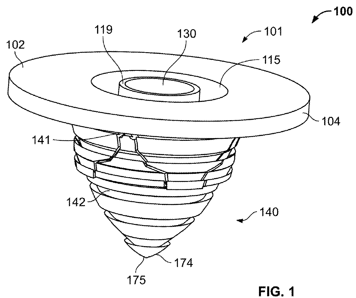
[0067]It should be understood that although the term “stemless implant” is used herein, the term does not indicate that a stemless implant fully lacks any anchor, but rather a stemless implant may include an anchor that is significantly smaller and / or shorter than stems of typical known stemmed implants. Further, the stemless implants of the present disclosure generally include a base member intended for coupling to an end of a first bone of a joint, such as a humerus or femur, and an articulating member intended to attach to the base member and to provide articulation with the second bone of the joint (or a corresponding prosthesis attached to the second bone). Further, as used herein, the term “proximal” refers to a location closer to an individual's heart, and the term “distal” refers to a location farther away from the individual's heart. When used in the context of an implant, the terms “proximal” and “distal” refer to locations on the implant closer to, or farther away from, t...


PUM


Abstract

A stemless prosthetic shoulder joint may include a prosthetic humeral head and a stemless base. The stemless base may include a collar and an anchor extending from the collar intended to anchor the base into the proximal humerus. The anchor may include various features to enhance the fixation of the base, including hooks, threads, and/or expandable members that may be transitioned from a contracted insertion condition to an expanded implanted condition once the base is positioned in the bone. The anchor and/or collar may also include additional features to enhance fixation, such as geometries and surface features to enhance fixation to bone. The anchor may include a plurality of chisel slots to facilitate removal of bone during a revision surgery.

Description

CROSS-REFERENCE TO RELATED APPLICATIONS[0001]This application claims the benefit of the filing date of U.S. Provisional Patent Application No. 62 / 474,800, filed Mar. 22, 2017, and U.S. Provisional Patent Application No. 62 / 542,396, filed Aug. 8, 2017, the disclosures of which are hereby incorporated herein by reference as if fully set forth herein.FIELD OF THE DISCLOSURE[0002]The present application relates to a shoulder prosthesis, and in particular to a humerus implant.BACKGROUND OF THE DISCLOSURE[0003]Over time and through repeated use, bones and joints can become damaged or worn. For example, repetitive strain on bones and joints (e.g., through athletic activity), traumatic events, and certain diseases (e.g., arthritis) can cause cartilage in joint areas, for example, which normally provides a cushioning effect, to wear down. When the cartilage wears down, fluid can accumulate in the joint areas, resulting in pain, stiffness, and decreased mobility. The same can happen in cases ...

Claims


Application Information

Patent Timeline
Patent Type & Authority Applications(United States)
IPC IPC(8): A61F2/40
CPCA61F2/4014A61F2002/30433A61F2002/30477A61F2002/4018A61F2002/30205A61F2002/30235A61F2002/30507A61F2002/30571A61F2002/30578A61F2002/30579A61F2002/30594A61F2002/30779A61F2002/3082A61F2002/30822A61F2002/30841A61F2002/30845A61F2002/3085A61F2002/30881A61F2002/30884A61F2002/3092A61F2002/4619A61F2/4003A61F2/4612A61F2002/30332A61F2002/4037A61F2/4081A61F2002/4007A61F2/4637A61F2002/30199
Inventor KEMP, PHILIP T.NELSON, ANDREW J.HEINSOHN, JANYADAV, RAJANRAO, KOUSTUBHBARILE, GENNARO A.SANCHEZ-SOTELO, JOAQUINMEHTA, ASHISHPERUMAL, VENKATESWARANVISCARDI, DAVID
Owner HOWMEDICA OSTEONICS CORP
Why Eureka
Try Eureka