Shear

a shear tool and cutting tool technology, applied in the field of shear tools, can solve problems such as rough or jagged edges of cutting studs

Active Publication Date: 2018-09-27
MILWAUKEE ELECTRIC TOOL CORP
View PDF17 Cites 15 Cited by
  • Summary
  • Abstract
  • Description
  • Claims
  • Application Information

AI Technical Summary

Problems solved by technology

Furthermore, the cut studs may have rough or jagged edges.

Method used


Image

  • Shear
  • Shear
  • Shear

Examples


Embodiment Construction

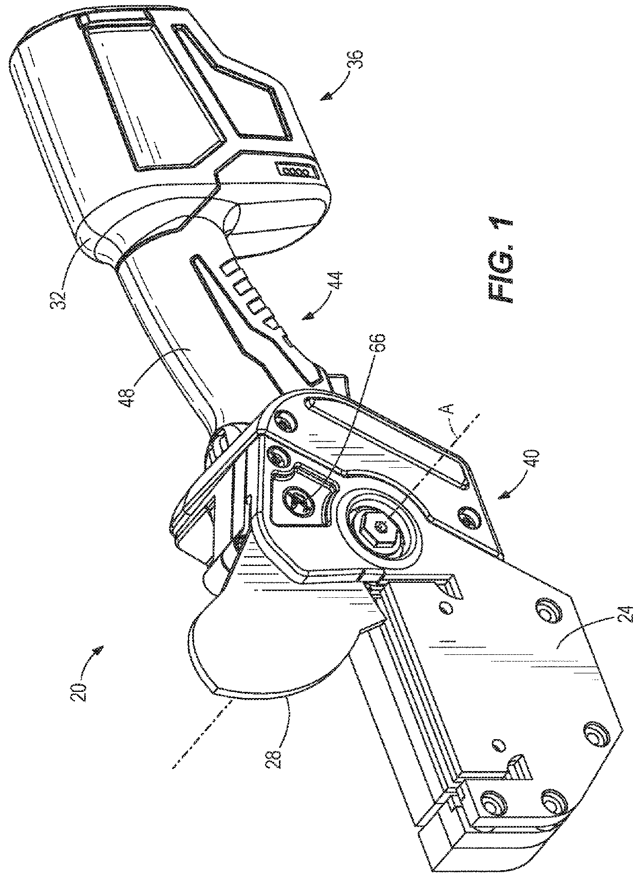
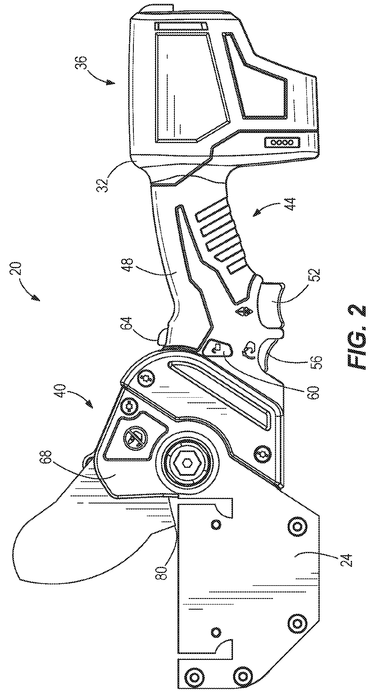
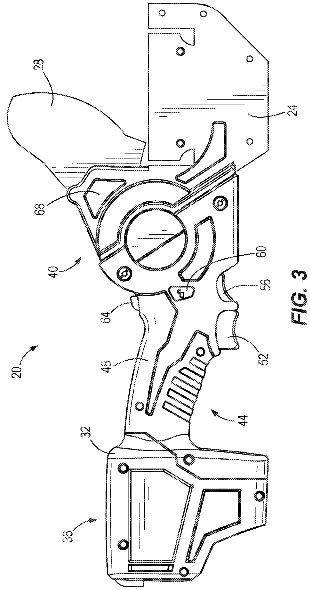
[0025]FIGS. 1-11 illustrate a power shear tool 20 for cutting or shearing materials. The power shear tool 20 of this embodiment receives, retains, and cuts construction material. More specifically, the power shear tool 20 includes a material receiving platform 24 that receives and retains a steel stud (FIG. 16) to be cut by a blade 28 of the power shear tool 20. As will be described in greater detail below, the power shear includes the blade 28 driven by a motor 30 (FIG. 9), which drives the blade 28 to cut a steel stud supported by the material receiving platform 24.

[0026]With reference to FIGS. 1-5, the power shear tool 20 includes a main housing 32 defining a battery receiving portion 36 and a tool head portion 40 with a handle portion 44 extending therebetween. The battery receiving portion 36 engages and supports a battery pack (not shown) that provides power to the tool 20. In one example, the battery pack may be a power tool battery pack having battery cells of various chemis...


PUM

PropertyMeasurementUnit
widthaaaaaaaaaa
widthsaaaaaaaaaa
widthsaaaaaaaaaa

Abstract

A power shear tool includes a housing portion, a motor positioned within the housing portion, and a tool head portion extending from the housing portion and including a blade rotatable relative to the tool head portion. The power shear tool includes a workpiece support member positioned proximate the tool head portion. The workpiece support member includes a top surface and a bottom surface opposite the top surface, side surfaces extending between the top and the bottom surfaces, a first channel defined in the top surface and extending from at least one of the side surfaces, and a second channel defined in the top surface. The second channel intersects the first channel and extends transverse to the first channel.

Description

CROSS REFERENCE TO RELATED APPLICATIONS[0001]This application claims priority to U.S. Provisional Patent Application No. 62 / 476,284 filed on Mar. 24, 2017, the contents of which are incorporated by reference herein.FIELD OF THE INVENTION[0002]The present invention relates to a shear tool, and more particularly to a power shear tool.BACKGROUND OF THE INVENTION[0003]There are various shear tools known in the art for cutting a workpiece such as a steel stud. Typically, these shear tools are able to cut only partially through the steel studs. Furthermore, the cut studs may have rough or jagged edges.SUMMARY OF THE INVENTION[0004]The invention provides, in one aspect, a power shear tool including a housing portion, a motor positioned within the housing portion, and a tool head portion extending from the housing portion and including a blade rotatable relative to the tool head portion. The power shear tool includes a workpiece support member positioned proximate the tool head portion. The...

Claims


Application Information

Patent Timeline
Patent Type & Authority Applications(United States)
IPC IPC(8): B23D29/02B26B15/00B23D17/02
CPCB23D29/02B26B15/00B23D17/02B23D17/04B23D23/00B23D29/00B23D35/001
Inventor PERKINS, KENNETH
Owner MILWAUKEE ELECTRIC TOOL CORP
Why Eureka
Try Eureka