Accessory Mounting System

Active Publication Date: 2018-09-27
WHELEN ENGINEERING COMPANY
View PDF10 Cites 2 Cited by
  • Summary
  • Abstract
  • Description
  • Claims
  • Application Information

AI Technical Summary

Benefits of technology

[0004]In the illustrated embodiment, an accessory mounting system (hereinafter, “system”) is disclosed. An accessory body encompasses and supports the portion of the system that is operational after the system has been assembled and mounted, one such accessory body being a lighthead. The disclosed system

Problems solved by technology

The fastener may pass through the light emitting (outward-facing) surface of the lighthead, thereby reducing the light-emitting surface area of the

Method used


Image

  • Accessory Mounting System
  • Accessory Mounting System
  • Accessory Mounting System

Examples


Example

[0016]An embodiment of an accessory mounting system according to aspects of the disclosure will now be described with reference to FIGS. 1-8, wherein like numerals represent like parts. The disclosed embodiment of a mounting system will generally be referred to by the reference numeral 10. Various materials, methods of construction, methods of manufacture, and methods of fastening will be discussed in the context of the disclosed embodiment. Those skilled in the art will recognize known substitutes for the materials, manufacturing methods, and fastening methods, all of which are contemplated as compatible with the disclosed embodiment and are intended to be encompassed by the appended claims.

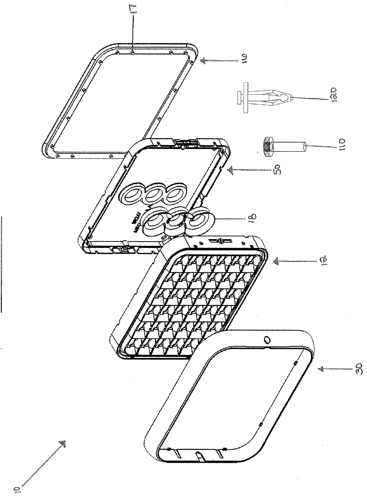
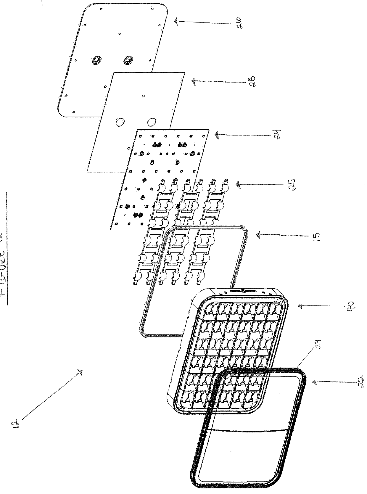
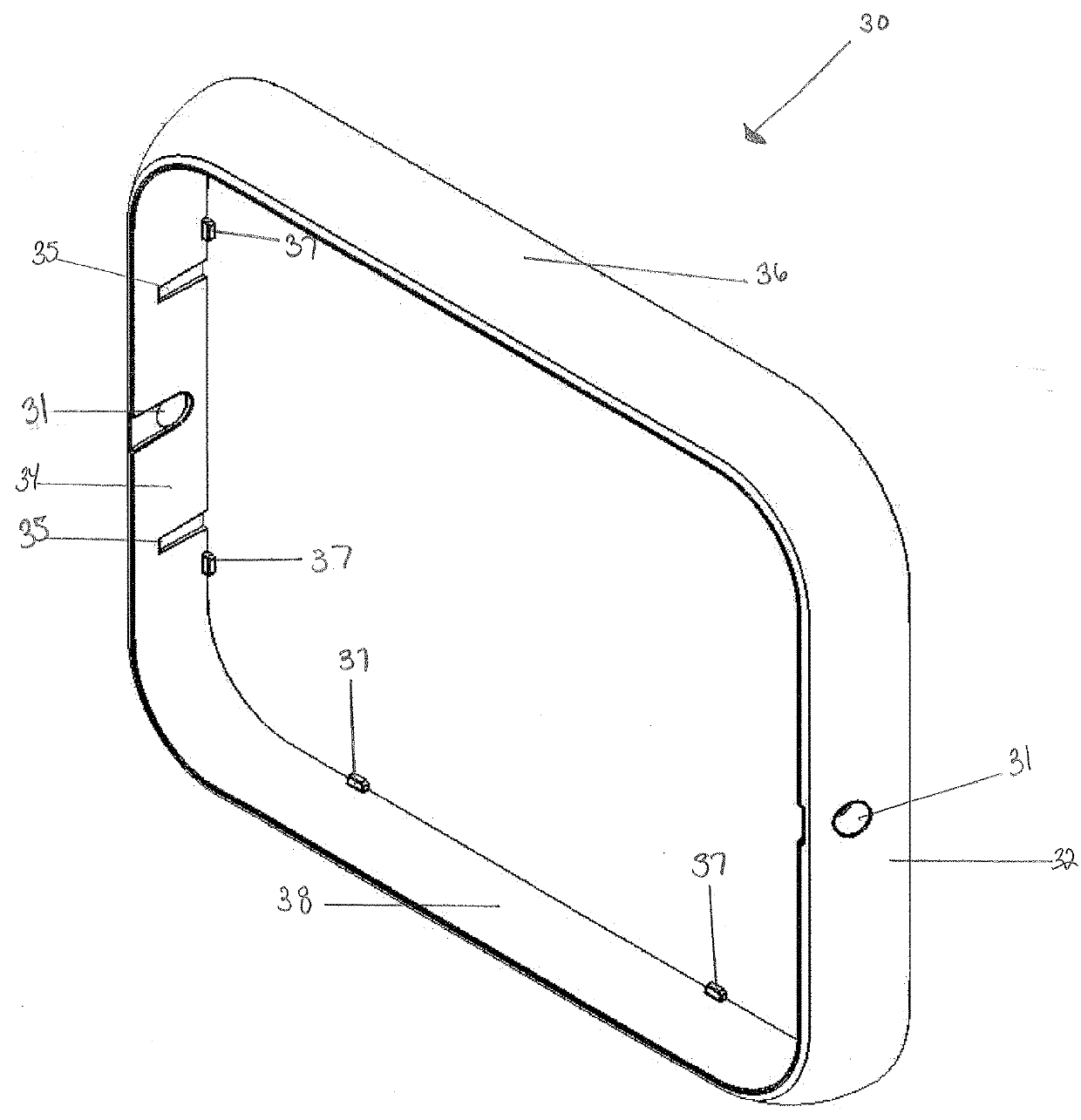
[0017]As shown in FIG. 1, an embodiment of the disclosed mounting system 10 includes a lighthead 12, a bezel 30, a frame 50 and a rear gasket 16. As shown in FIG. 2, the lighthead 12 is an assembly including a lens 22, a reflector 40, a lighthead seal 15, a printed circuit (PC) board 24, groups ...


PUM


Abstract

According to aspects of the disclosure, the system comprises a frame mounted in sealed relation to a surface. The frame includes movable engagement features and surfaces that mate with an accessory body. A gasket positioned between the frame and a mounting surface seals the space between the frame and the mounting surface from surrounding external elements. The frame may ‘be fastened to the mounting surface with tool-free rivet fasteners, or more conventional threaded fasteners. The assembled accessory body and bezel fit over the frame and the movable engagement features of the frame mate with complementary structures on the accessory body to fix the accessory body to the frame. Openings in the accessory body allow a threaded fastener to secure the movable engagement feature of the frame in the mated position, preventing unintentional disengagement of the accessory body.

Description

BACKGROUND[0001]The present disclosure relates to systems for mounting accessories to motor vehicles. More specifically, the disclosure relates to a system for mounting light-generating assemblies referred to as lightheads to motor vehicles.[0002]Lightheads for motor vehicles typically include a housing, light source, electrical circuitry, and connections to vehicle power and control devices for actuating the lighthead. A lighthead may be used on motor vehicles including vehicles deployed for law enforcement and emergency response, such as the warning lights on ambulances, fire engines and police vehicles. When used as a warning light, a lighthead must comply with various regulations and standards while also being able to function reliably when exposed to potentially damaging environmental conditions, including hot and cold temperature extremes, sunlight, moisture, dust, dirt and various chemicals such as ice melting compounds. Prior art lightheads have employed threaded fasteners t...

Claims


Application Information

Patent Timeline
IPC IPC(8): B60Q1/26
CPCB60Q1/2696B60Q1/2615F21S43/19F21S43/14
Inventor LYONS, JON H.
Owner WHELEN ENGINEERING COMPANY
Why Eureka
Try Eureka