Gas turbine engine and test cell real-time diagnostic fault detection and corrective action system and method

Active Publication Date: 2018-10-04
HONEYWELL INT INC
View PDF4 Cites 5 Cited by
  • Summary
  • Abstract
  • Description
  • Claims
  • Application Information

AI Technical Summary

Benefits of technology

The patent describes a real-time diagnostic and fault detection system for a gas turbine engine under test in a test cell. The system uses sensor data from instrumentation coupled to the engine to calculate parameters at non-instrumented locations within the engine using a physics-based model. The parameters are then processed to detect and identify faults in the engine, and to generate corrective actions to address the faults. The system can also predict whether the engine will pass the selected test conditions based on the calculated performance projections. The technical effects of the patent include improved accuracy and efficiency in detecting and addressing faults in gas turbine engines, leading to improved reliability and performance.

Problems solved by technology

Unfortunately, current test cell capabilities result in the root-causes / anomalies associated with an unsuccessful engine test to be found post-test.
This is a reactive process that can result in repeat testing, negative schedule impacts, missed test objectives, inconsistent test runs, potential engine damage, and delayed shipment of engines.
All of which can lead to increased overall costs.

Method used


Image

  • Gas turbine engine and test cell real-time diagnostic fault detection and corrective action system and method
  • Gas turbine engine and test cell real-time diagnostic fault detection and corrective action system and method
  • Gas turbine engine and test cell real-time diagnostic fault detection and corrective action system and method

Examples


Embodiment Construction

[0016]The following detailed description is merely exemplary in nature and is not intended to limit the invention or the application and uses of the invention. As used herein, the word “exemplary” means “serving as an example, instance, or illustration.” Thus, any embodiment described herein as “exemplary” is not necessarily to be construed as preferred or advantageous over other embodiments. All of the embodiments described herein are exemplary embodiments provided to enable persons skilled in the art to make or use the invention and not to limit the scope of the invention which is defined by the claims. Furthermore, there is no intention to be bound by any expressed or implied theory presented in the preceding technical field, background, brief summary, or the following detailed description.

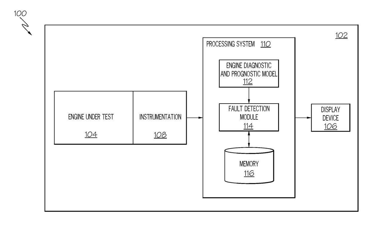
[0017]Referring now to FIG. 1, a functional block diagram of one embodiment of a real-time diagnostic and fault detection system 100 is depicted. The system 100 is preferably implemented in a t...


PUM


Abstract

A real-time diagnostic and fault detection system and method for a gas turbine engine under test in a test cell is disclosed. Sensor data from instrumentation coupled to the gas turbine engine are processed, using a physics-based component level aero-thermal model, to calculate a plurality of engine parameters at a plurality of non-instrumented locations within the gas turbine engine. The plurality of engine parameters are processed to detect when a fault exists and, when a fault does exist, an image is rendered that indicates at least a mostly likely cause for the fault and one or more corrective actions that can be taken to correct the fault. The model is also used to generate projections of engine performance at one or more selected test conditions, and to prognosticate, based on the projections, as to whether the gas turbine engine will actually pass at the one or more selected test conditions.

Description

TECHNICAL FIELD[0001]The present invention generally relates to gas turbine engine, and more particularly relates to systems and methods for providing real-time diagnostic fault detection and corrective action for gas turbine engines under test in a test cell as well as predict engine performance.BACKGROUND[0002]Gas turbine engines may undergo various performance and design tests. These tests may occur, for example during engine design and development, production, or following overhaul, repair, or inspection of the engine. Such tests are typically performed in a test cell, and demonstrate that the engine can meet its design, operational, and safety requirements.[0003]As is generally known, a test cell is a closed facility that includes extensive instrumentation and allows for various on-wing environmental simulations. In a typical test cell, the engine under test is installed in, for example, a thrust frame, which is similar in construction to an aircraft engine mount. The thrust fr...

Claims


Application Information

Patent Timeline
IPC IPC(8): F01D21/00G01M15/14
CPCF01D21/003F05D2220/32G01M15/14F05D2260/80F05D2260/83
Inventor GILL, CHRISTOPHERVEDDER, CURTISMOECKLY, KEVIN
Owner HONEYWELL INT INC
Why Eureka
Try Eureka