Driving apparatus, gimbal, imaging device, aerial vehicle and movable device

Active Publication Date: 2018-10-04
SZ DJI OSMO TECH CO LTD
View PDF6 Cites 3 Cited by
  • Summary
  • Abstract
  • Description
  • Claims
  • Application Information

AI Technical Summary

Benefits of technology

[0142]The transmission member of the driving mechanism, the imaging device, the gimbal, the aerial vehicle and the movable device as discussed hereinabove can be movably wound around the circumference of the rotor, and then connected to the electrical component on the carrying member, such that the transmission member can have an excess length to accommodate the variation in the relative position and/or relative distance between the supp

Problems solved by technology

However, the dedicated part for winding the wire can be large, thus a volume

Method used


Image

  • Driving apparatus, gimbal, imaging device, aerial vehicle and movable device
  • Driving apparatus, gimbal, imaging device, aerial vehicle and movable device
  • Driving apparatus, gimbal, imaging device, aerial vehicle and movable device

Examples


Example

LIST OF REFERENCE NUMERALS

[0149]

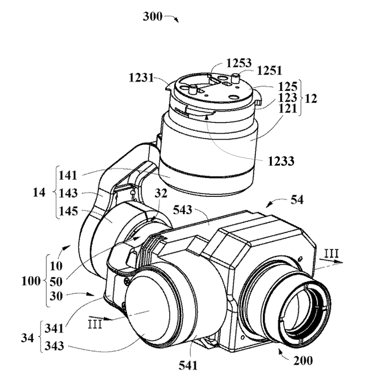
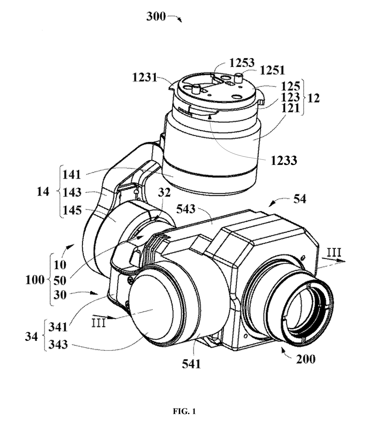
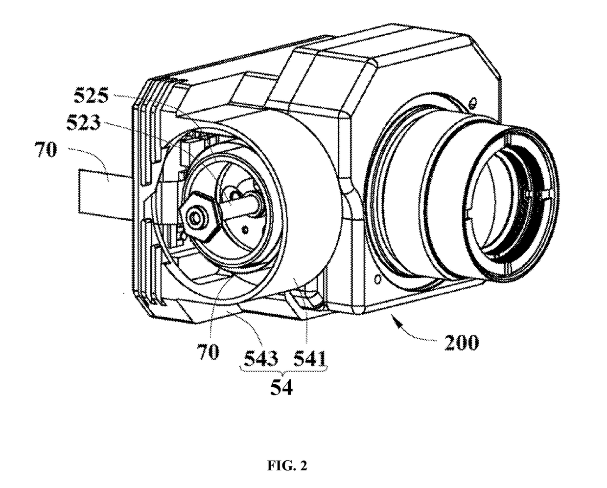
TABLE 1Imaging device300Gimbal100First frame10Mounting assembly12Receiving member121Fitting member123Fitting portion1231Guiding surface1233Cap member125Positioning portion1251Through hole1253Connecting member14Coupling portion141Connecting arm143Connecting portion145Second frame30Support driver32Support34Supporting arm341Mounting portion343Third frame50Carrying member driver52Stator521Rotating shaft523Rotor525Carrying member54Receiving portion541Carrying portion543Assembling portion545Bottom wall5451Connecting hole5452, 5454, 5431Top wall5455Side wall5453First fitting portion5456Accommodating space547Auxiliary controller60Transmission member70Image capturing apparatus200Joint portion201Second fitting portion205Connector207

[0150]The present disclosure will be described in the illustrative embodiments by reference to the drawings.

DETAILED DESCRIPTION OF THE DISCLOSURE

[0151]A better understanding of the disclosure will be obtained by reference to the fol...


PUM


Abstract

A gimbal includes a support, a carrying member carrying an electrical component, a carrying member driver coupled to the support and the carrying member, and a transmission member in the support. The carrying member driver is configured to drive the carrying member to rotate relative to the support. The carrying member driver includes a stator coupled to the support, and a rotor sleeving outside the stator and being coupled to the carrying member. The transmission member extends from within the support, winds around a circumference of the rotor, and extends to the carrying member to be electrically connected with the electrical component.

Description

CROSS-REFERENCE TO RELATED APPLICATION[0001]This application is a continuation of International Application No. PCT / CN2015 / 097068, filed on Dec. 10, 2015, the entire contents of which are incorporated herein by reference.TECHNICAL FIELD[0002]The present disclosure relates to a driving apparatus. The present disclosure also relates to a gimbal, an imaging device, an aerial vehicle and a movable device having the driving apparatus.BACKGROUND OF THE DISCLOSURE[0003]An electronic apparatus such as a video camera or an image camera can be carried on an electric gimbal to perform an image capturing. The electronic apparatus can be electrically connected to electrical components of the gimbal to transmit data or electric power. The gimbal can be a two-axis gimbal or a three-axis gimbal, and the electronic apparatus can be coupled to an end shaft of the gimbal and driven by the gimbal to change an imaging attitude. A relative long electrical wire can be used in connecting the electronic app...

Claims


Application Information

Patent Timeline
IPC IPC(8): G03B17/56F16M11/10F16M11/20F16M13/02B64D47/08G03B15/00
CPCG03B17/561F16M11/10F16M11/2071F16M13/02B64D47/08G03B15/006B64C39/024B64C2201/127F16M11/18F16M13/022F16M2200/041F16M2200/044B64U2101/30
Inventor YAN, XIN
Owner SZ DJI OSMO TECH CO LTD
Why Eureka
Try Eureka