

Reactive force generation device
- Summary
- Abstract
- Description
- Claims
- Application Information
AI Technical Summary
Benefits of technology
Problems solved by technology
Method used
Image

Examples
first embodiment
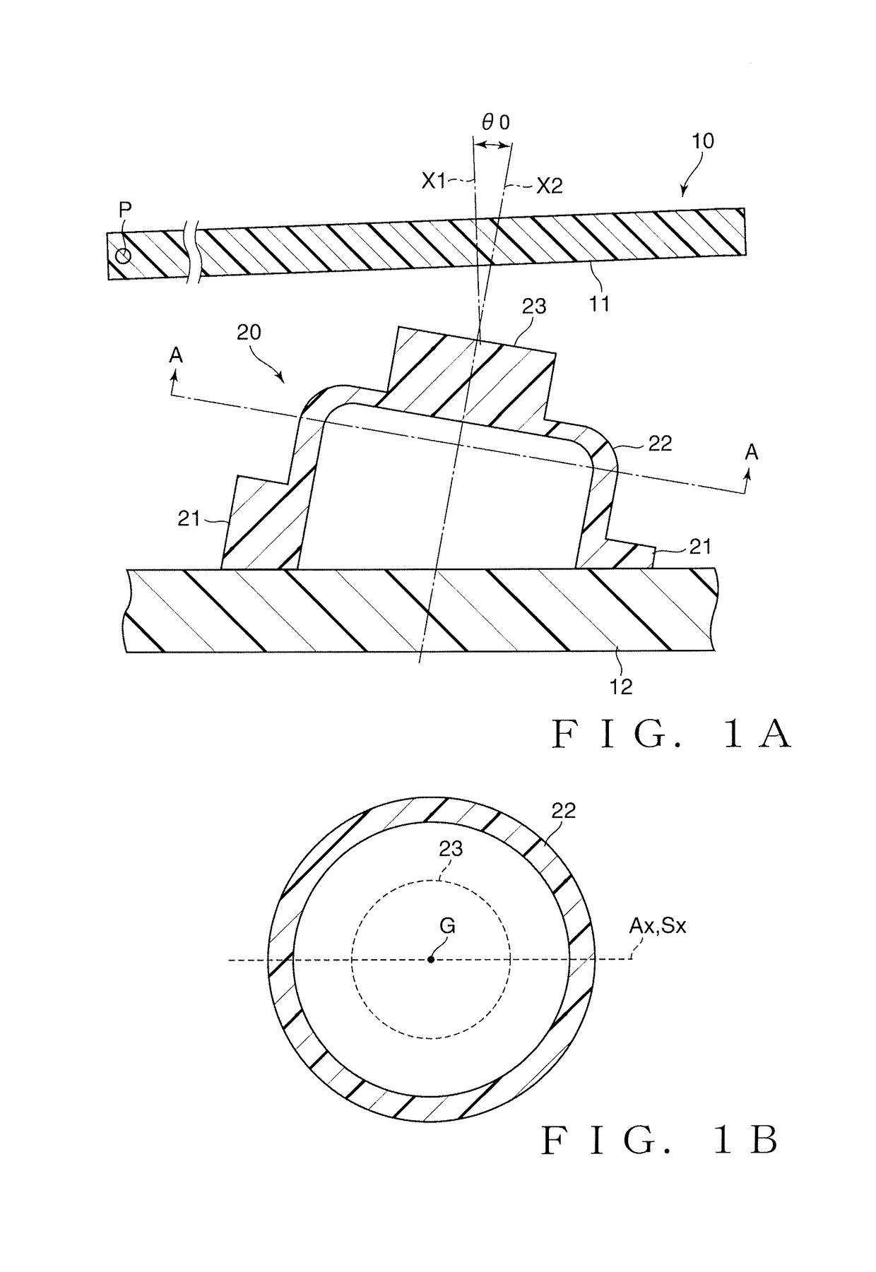
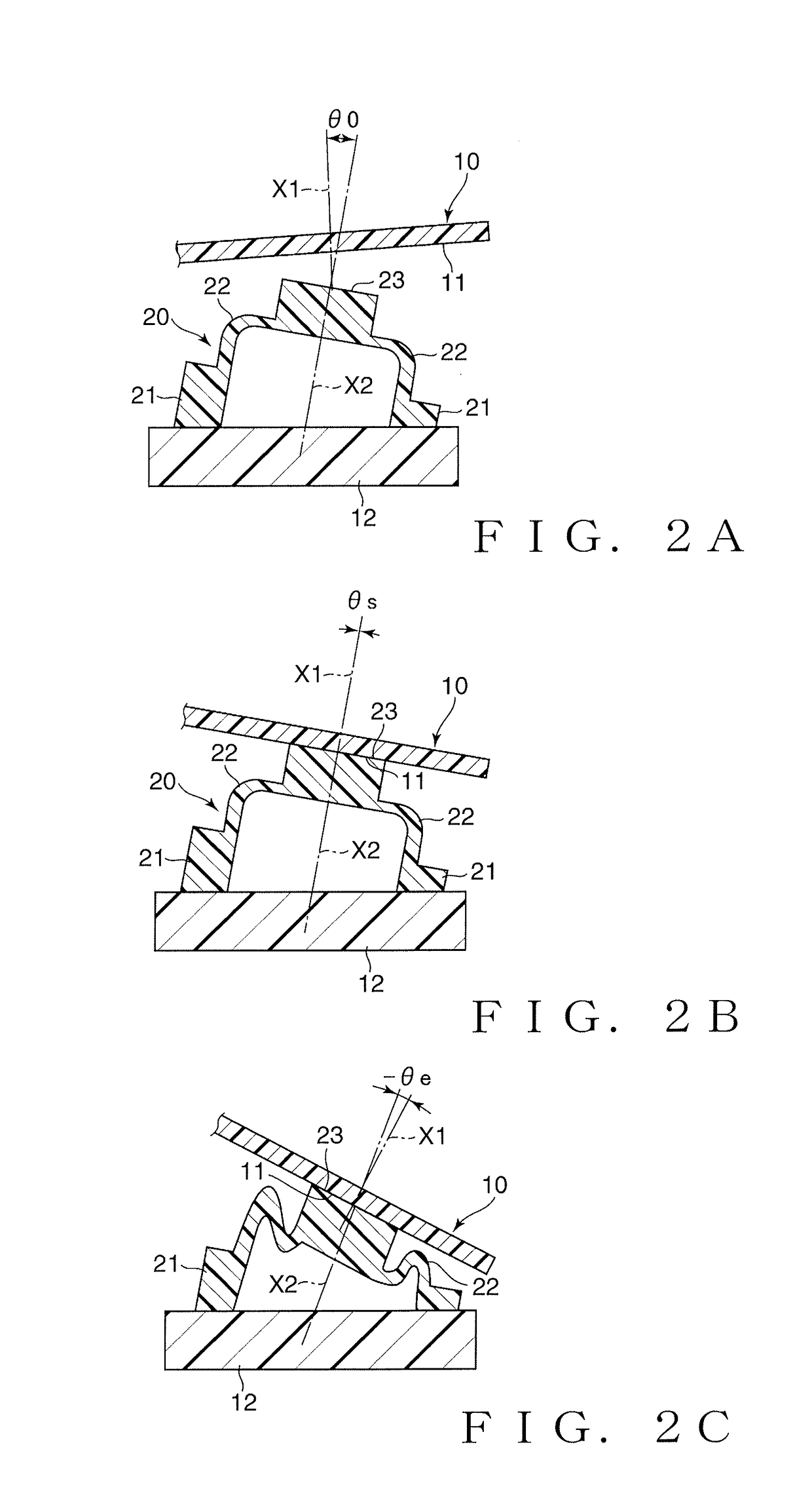
[0016]FIG. 1A is a schematic sectional view showing a construction of a reactive force generation device according to a first embodiment of the present invention. This reactive force generation device includes at least a first member 10 and a to-be-depressed member 20 depressible by the first member 10 (i.e., an opposed member 10). The to-be-depressed member 20 is disposed on a second member 12. As an example, the first member 10 is pivotable, or displaceable while making a swaying or swinging movement, within a given angle range about a pivot shaft (or swing shaft) P. Namely, the first member 10 is capable of making stroke movements by pivoting or swinging about the pivot shaft (or swing shaft) P. The first member 10 may itself be a part of a manual operator (not shown) operable by a user, or may be a displacement member that is provided separately from the manual operator but displaceable in interlocked relation to a user's operation of the not-shown manual operator. The second me...
second embodiment
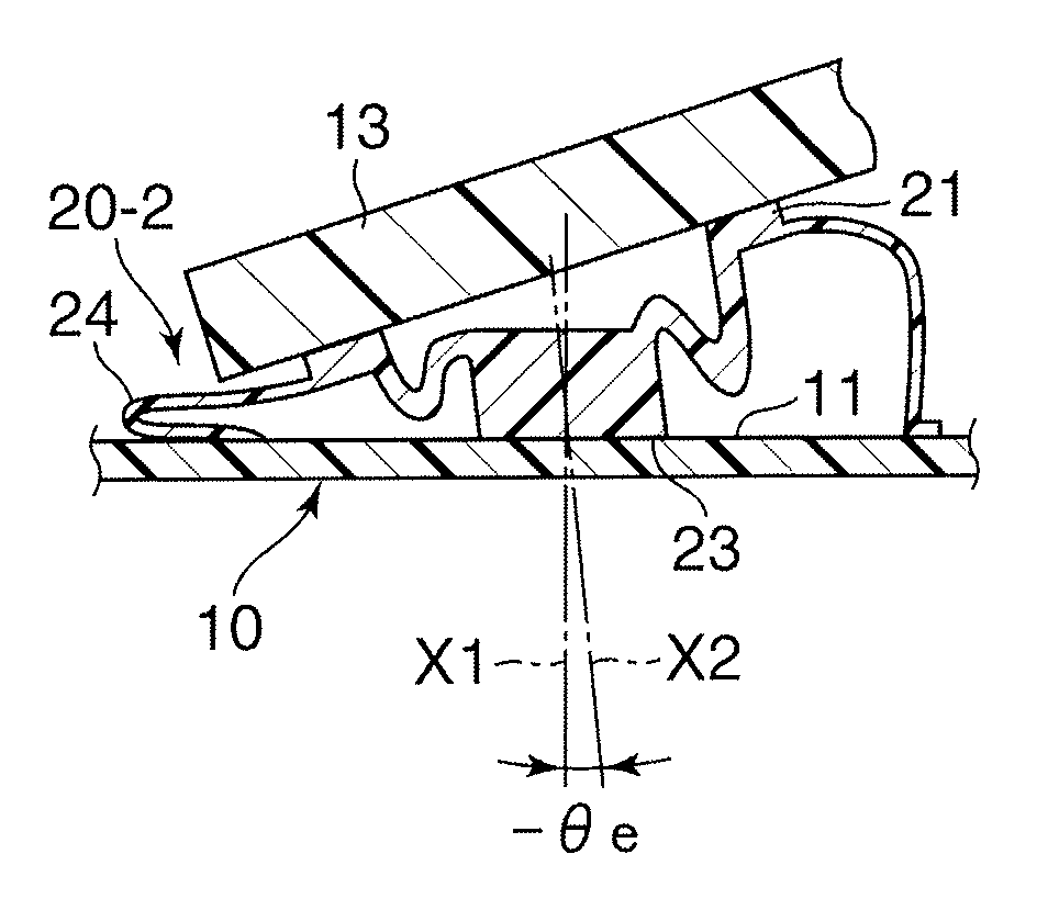
[0026]The following describe a reactive force generation device according to a second embodiment of the present invention, which is characterized by a construction for causing a depressing member 13 to depress the base section 21. FIGS. 4A, to 4D are diagrams showing a state transition of the to-be-depressed member 20-2 during the depression stroke in the second embodiment. The to-be-depressed member 20-2 is generally similar to the to-be-depressed member 20 described above in relation to the first embodiment, except that it includes a skirt section 24 having elasticity. In the illustrated example, the base section 21 is held on the first member 10 via the elastic skirt section 24. The base section 21 and the dome section 22 (having the distal end 23) are substantially similar in construction to those of the to-be-depressed member 20 shown in FIG. 1A. Note that the skirt section 24 is deformable sufficiently more easily than the dome section 22 and hence does not greatly contribute ...
third embodiment
[0031]In the above-described first and second embodiments of the present invention, the first member 10 or the depressing member 13 is constructed to make a pivotal or swinging movement about one fixed pivot shaft P. However, the present invention is not necessarily so limited, and the basic principles of the present invention are also applicable to other constructions or designs that make complicated stroke movements, such as one where a swinging movement axis (center of swinging movement) is displaced during the depression stroke. FIG. 5 is a schematic sectional view showing an embodiment of the present invention applied to the construction where the swinging movement axis (or a virtual swinging movement axis) is displaced during the depression stroke. In FIG. 5, elements indicated by the same reference numerals and characters as in FIG. 1A function in substantially the same manner as the corresponding elements described above with reference to FIG. 1A and thus will not be describ...
PUM
 Abstract
Description
Claims
Application Information