Method and device for coding residual signal in video coding system

Active Publication Date: 2018-10-04
LG ELECTRONICS INC
View PDF4 Cites 21 Cited by
  • Summary
  • Abstract
  • Description
  • Claims
  • Application Information

AI Technical Summary

Benefits of technology

[0013]According to the present invention, it is possible to increase coding efficiency of a residual signal.
[0014]According to the present invention, transform coefficients can be derived by using less bits. As a result, a quantity of data required for a res

Problems solved by technology

Therefore, when image data is transmitted using a medium such as a conventional wired/wireless broadband line or ima

Method used


Image

  • Method and device for coding residual signal in video coding system
  • Method and device for coding residual signal in video coding system
  • Method and device for coding residual signal in video coding system

Examples


Embodiment Construction

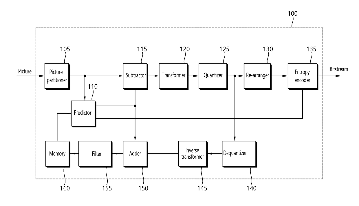
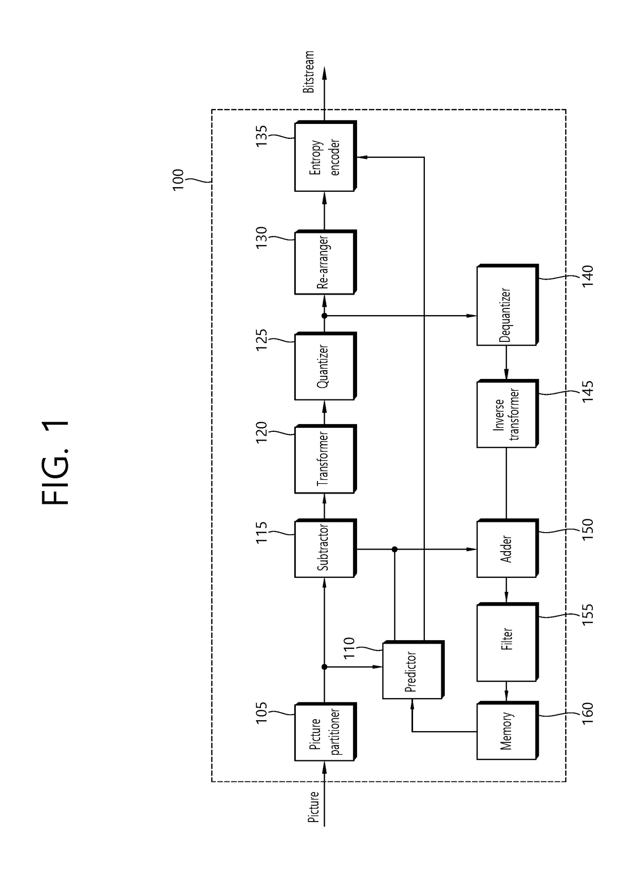
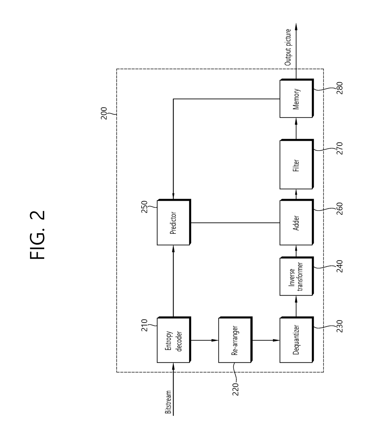
[0030]The present invention may be modified in various forms, and specific embodiments thereof will be described and illustrated in the drawings. However, the embodiments are not intended for limiting the invention. The terms used in the following description are used to merely describe specific embodiments, but are not intended to limit the invention. An expression of a singular number includes an expression of the plural number, so long as it is clearly read differently. The terms such as “include” and “have” are intended to indicate that features, numbers, steps, operations, elements, components, or combinations thereof used in the following description exist and it should be thus understood that the possibility of existence or addition of one or more different features, numbers, steps, operations, elements, components, or combinations thereof is not excluded.

[0031]On the other hand, elements in the drawings described in the invention are independently drawn for the purpose of co...


PUM


Abstract

An image decoding method according to the present invention comprises the steps of: deriving quantized transform coefficients by unit of sub-blocks in a transform unit on the basis of residual information included in a bitstream; deriving transform coefficients on the basis of the quantized transform coefficients; generating a residual sample on the basis of the transform coefficients; generating a prediction sample on the basis of an inter prediction or an intra prediction; and restoring an image on the basis of the residual sample and the prediction sample. According to the present invention, a quantity of data required for a residual signal can be reduced, and an overall coding efficiency can be improved.

Description

BACKGROUND OF THE INVENTIONField of the Invention[0001]The present invention relates to technology for video coding, and more particularly, to a method and a device for coding a residual signal in a video coding system.Related Art[0002]Demand for high-resolution, high-quality images such as HD (High Definition) images and UHD (Ultra High Definition) images has been increasing in various fields. As the image data has high resolution and high quality, the amount of information or bits to be transmitted increases relative to the legacy image data. Therefore, when image data is transmitted using a medium such as a conventional wired / wireless broadband line or image data is stored using an existing storage medium, the transmission cost and the storage cost thereof are increased.[0003]Accordingly, there is a need for a highly efficient image compression technique for effectively transmitting, storing, and reproducing information of high resolution and high quality images.SUMMARY OF THE IN...

Claims


Application Information

Patent Timeline
IPC IPC(8): H04N19/105H04N19/124H04N19/176H04N19/44H04N19/61H04N19/18
CPCH04N19/105H04N19/124H04N19/176H04N19/44H04N19/61H04N19/18H04N19/70H04N19/119H04N19/129H04N19/14H04N19/90
Inventor HEO, JINSON, EUNYONGLEE, JAEHOPARK, SEUNGWOOKYEA, SEHOONNAM, JUNGHAK
Owner LG ELECTRONICS INC
Why Eureka
Try Eureka