Ammunition storage system

a technology of ammunition storage and storage system, which is applied in the field of remote control weapon stations or systems, can solve the problems of inoptimum solution, complicated bracket, and complex mechanical devices with many moving parts, and achieve the effect of convenient folding and easy loading

Active Publication Date: 2018-10-18
MOOG INC
View PDF0 Cites 4 Cited by
  • Summary
  • Abstract
  • Description
  • Claims
  • Application Information

AI Technical Summary

Benefits of technology

[0013]An ammunition container formed in accordance with a second embodiment of the invention operates in the manner of a spool. The ammunition container of the second embodiment generally comprises a pair of parallel side walls, an ammunition clamp mounted between the pair of side walls for rotation about a clamp axis extending normal to the pair of side walls, a keeper movable relative to the pair of parallel side walls. The ammunition clamp is configured to clamp a single round of ammunition such that the round extends parallel to the clamp axis, and the ammunition clamp is rotatable about the clamp axis to wind a belt of ammunition about the clamp axis. The keeper is biased to exert force on a portion of a wound ammunition belt in a direction toward the clamp axis to maintain the ammunition belt in a wound condition as the ammunition belt is fed to a weapon. An outfeed roller may be provided to help guide the rounds of the ammunition belt as they exit the container on their way to a weapon.
[0014]An ammunition container formed in accordance with a third embodiment of the invention is configured for manual reloading such that the belt of ammunition is guided into the container and may be easily folded over onto itself to form horizontal layers. The ammunition container of the third embodiment comprises a pair of transversely spaced side walls and a bottom wall connecting the pair of side walls. The side walls define an internal space between them, an exit opening at a top front region of the container, and a loading access opening at a top rear of the container. The ammunition container of the third embodiment further comprises sprocket positioned proximate to the loading access opening, and a transversely extending peg fixed relative to the pair of side walls at a location above and behind the sprocket. The sprocket is rotatable about a transverse sprocket axis relative to the pair of side walls to guide rounds of ammunition through the loading access opening and into the internal space. The peg enables a new belt of linked ammunition to be suspended vertically adjacent the sprocket as the belt is being loaded into the container.
[0015]An ammunition container formed in accordance with a fourth embodiment of the present invention is an improved version of a hanging ammunition container. The ammunition container of the fourth embodiment comprises a pair of transversely spaced side walls connected by at least one transverse bride member. The pair of side walls define an internal space between them, and also define a rear opening and a bottom opening continuous with the rear opening, wherein the rear and bottom openings allow access to the internal space. The ammunition container further comprises a pair of longitudinal support rails respectively mounted to corresponding inner surfaces of the pair of side walls. Each of the support rails may extend through the rear opening of the container such that a rear end of each support rail is located outside of the internal space for easier loading.

Problems solved by technology

These systems also require multi-axis motion to load ammunition, namely rotation about the central axis and translation along the central axis, which in turn has led to mechanically complex devices with many moving parts.
While the system enables reloading under armored protection, it requires a mechanically complicated bracket and uses space within the vehicle compartment to accommodate the lowered ammunition container during reloading.
Given that the vehicle compartment is already very confined, this solution is not optimal.
Here again, the system enables reloading under armored protection, but it requires an elevator mechanism and uses valuable space within the vehicle compartment.

Method used


Image

  • Ammunition storage system
  • Ammunition storage system
  • Ammunition storage system

Examples


first embodiment

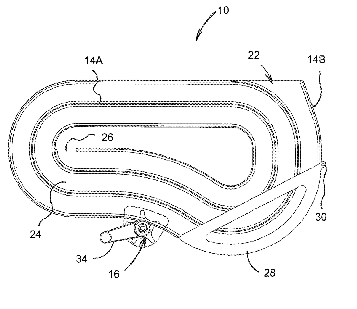
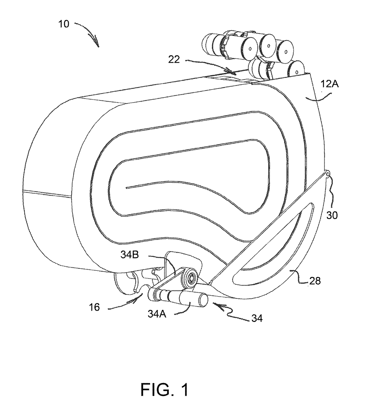
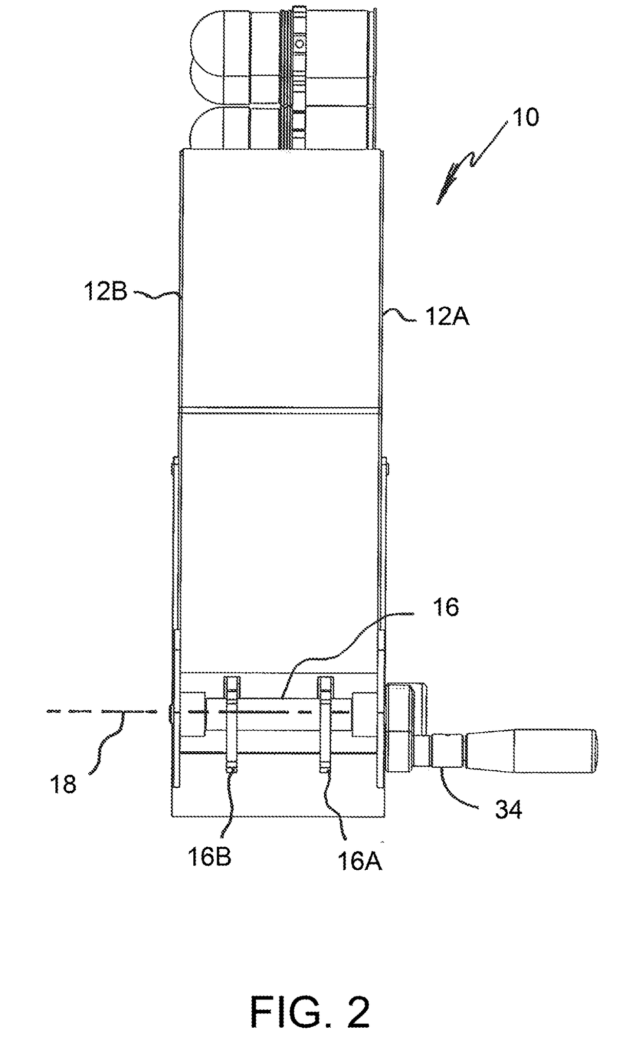
[0049]FIGS. 1-4 show an ammunition container 10 formed in accordance with the present invention. Ammunition container 10 is useful for storing a belt of linked ammunition within an internal compartment of an RWS turret mounted on an armored vehicle, wherein the ammunition belt is fed round-by-round to an external weapon of the RWS. More particularly, ammunition container 10 is configured to be safely reloaded by personnel inside the armored vehicle without disconnecting or removing rounds between an exit opening of the container and the weapon, and provides space-efficient storage of ammunition in a confined environment.

[0050]Ammunition container 10 of the first embodiment generally comprises a pair of parallel side walls 12A, 12B, at least one guide wall 14A, 14B connecting the pair of side walls, and a sprocket 16 rotatable about a sprocket axis 18 extending normal to the pair of side walls. As may be understood from FIG. 3, the at least one guide wall 14A, 14B defines a loading a...

second embodiment

[0061]A process of reloading ammunition container 40 of the second embodiment will now be described with reference to FIGS. 11-14. FIG. 11 shows ammunition container 40 as it is becoming depleted of a prior ammunition belt 2 having individual rounds 3. Belt 2 is pulled in a weapon feed direction by a feed mechanism associated with an automatic weapon. As may be seen, a trailing round 3Z of belt 2 is clamped in ammunition clamp 46. To reload ammunition container 10, keeper 54 is opened outward as shown in FIG. 12, trailing round 3Z of prior ammunition belt 2 is pulled out of ammunition clamp 46 to permit a trailing portion of belt 2 to unwind, and a trailing round 5Z of new belt 4 is inserted through loading access opening 56 and clamped in ammunition clamp 46. As illustrated in FIG. 13, ammunition clamp 46 is then rotated clockwise to wind new belt 4 onto itself. A leading round 5A of new belt 4 will emerge from ammunition box 1 and is clipped onto the trailing round 3Z of prior amm...

third embodiment

[0064]Ammunition container 70 of the third embodiment generally comprises a pair of transversely spaced side walls 72A, 72B and a bottom wall 74 connecting side walls 72A, 72B, wherein the pair of side walls define an internal space 75 between them. Side walls 72A, 72B also define an exit opening 82 at a top front region of container 70 and a loading access opening 80 at a top rear of the container. As shown in FIGS. 15-18, side walls 72A, 72B may be parallel to one another.

[0065]Ammunition container 70 further comprises a sprocket 76 positioned proximate to loading access opening 80, wherein sprocket 76 is rotatable about a transverse sprocket axis 78 relative to side walls 72A, 72B to guide rounds of ammunition through loading access opening 80 and into the internal space 75. Sprocket 76 may include a first sprocket wheel 76A and a second sprocket wheel 76B each having teeth 77 (see FIG. 19) angularly spaced about sprocket axis 78 to define recesses for receiving individual rounds...


PUM


Abstract

Ammunition containers are reloadable from within an armored vehicle to supply a remote weapon system mounted externally on the vehicle. The ammunition containers are designed to be fixedly mounted within an internal compartment of a weapon turret. In a first embodiment, at least one guide wall defines a spiral guide path for an ammunition belt, and a rotatable sprocket enables the belt to be loaded into the guide path. In a second embodiment, an ammunition clamp holds a round of ammunition, and the clamp is rotatable to wind the ammunition belt about the clamp's axis of rotation. A third embodiment has a guide sprocket and an adjacent peg to facilitate reloading an ammunition belt in horizontal layers. A fourth embodiment includes a pair of spaced support rails for hanging an ammunition belt in vertical columns, wherein rear ends of the rails may be located outside the container for easier loading.

Description

FIELD OF THE INVENTION[0001]The present invention relates generally to the field of remote-controlled weapon stations or systems (RWSs) designed to mount over a hatch opening in a top deck of an armored vehicle, and more particularly to ammunition storage systems for storing and supplying linked ammunition to weapons of the externally-mounted RWS from within the armored vehicle.BACKGROUND OF THE INVENTION[0002]Vehicle-mounted RWSs are retrofittable to various types of military vehicles, including but not limited to armored combat vehicles (ACVs), mine-resistant ambush protected (MRAP) vehicles, armored multi-purpose vehicles (AMPVs), amphibious assault vehicles (AAVs), and light armored vehicles (LAVs). The RWS allows personnel to operate externally-mounted weapons from the within the armored protection of the vehicle.[0003]An RWS may be outfitted with selected weapons (e.g. guns and missile launchers), and non-lethal operating units (e.g. target sighting units, acoustic hailers, an...

Claims


Application Information

Patent Timeline
Patent Type & Authority Applications(United States)
IPC IPC(8): F41A9/30F41A9/86
CPCF41A9/30F41A9/86
Inventor LUNG, KEVINHAYES, STEVEN W.MARTINEZ, MATTHEWRHODES, DAVIDMUELLER, FRANK
Owner MOOG INC
Why Eureka
Try Eureka