Eureka AIR delivers breakthrough ideas for toughest innovation challenges, trusted by R&D personnel around the world.

Ball channel assembly

Active Publication Date: 2018-10-25
BURTON TECH
View PDF0 Cites 7 Cited by
  • Summary
  • Abstract
  • Description
  • Claims
  • Application Information

AI Technical Summary

Benefits of technology

The present invention is a ball channel assembly that allows for easy insertion of a ball stud, while also allowing the ball stud to pivot and slide within the channel. Additionally, the assembly provides significant resistance to pulling out the ball stud.

Problems solved by technology

This configuration results in a condition where the ball stud may be pulled out of socket under certain conditions of operation, such as vibration while supporting heavier reflectors or in heavier headlamp assemblies, like the one previously referenced in U.S. Pat. No. 5,360,282, leaving the adjuster non-operational.
Though pull-out of the ball stud is resisted to some degree of success, if enough pull-out force is applied, the tabs deflect and the ball stud head slips through and “pops out.” Reducing the flexibility of tabs is not a desirable option because it would either be too difficult to insert the ball stud head into socket, or the elasticity of the tabs would be lessened to the degree that they would break off during insertion of the ball stud.
Most existing ball-sockets are not able to achieve such a low insertion force without sacrificing pull out resistance due to their construction.
Unfortunately, it is often desired to achieve a pull-out force resistance of 400N or higher.
This design does not, however, permit sliding movement.

Method used


Image

  • Ball channel assembly
  • Ball channel assembly
  • Ball channel assembly

Examples


Embodiment Construction

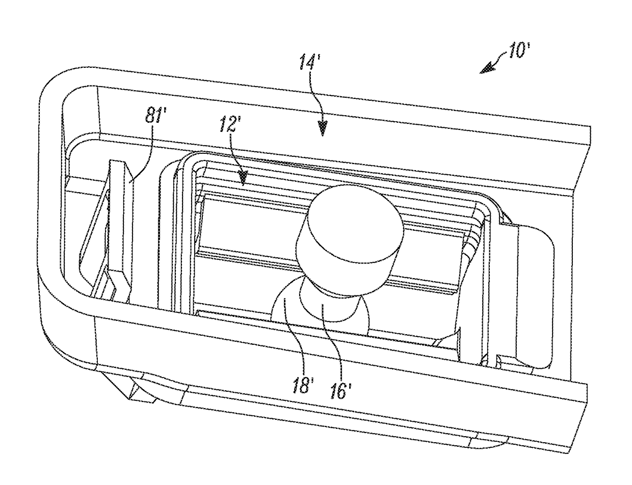
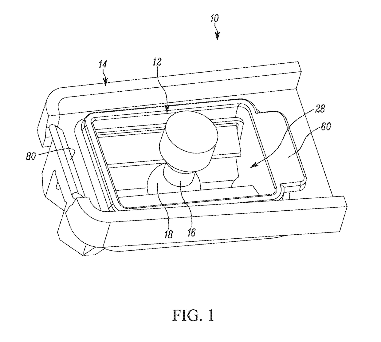
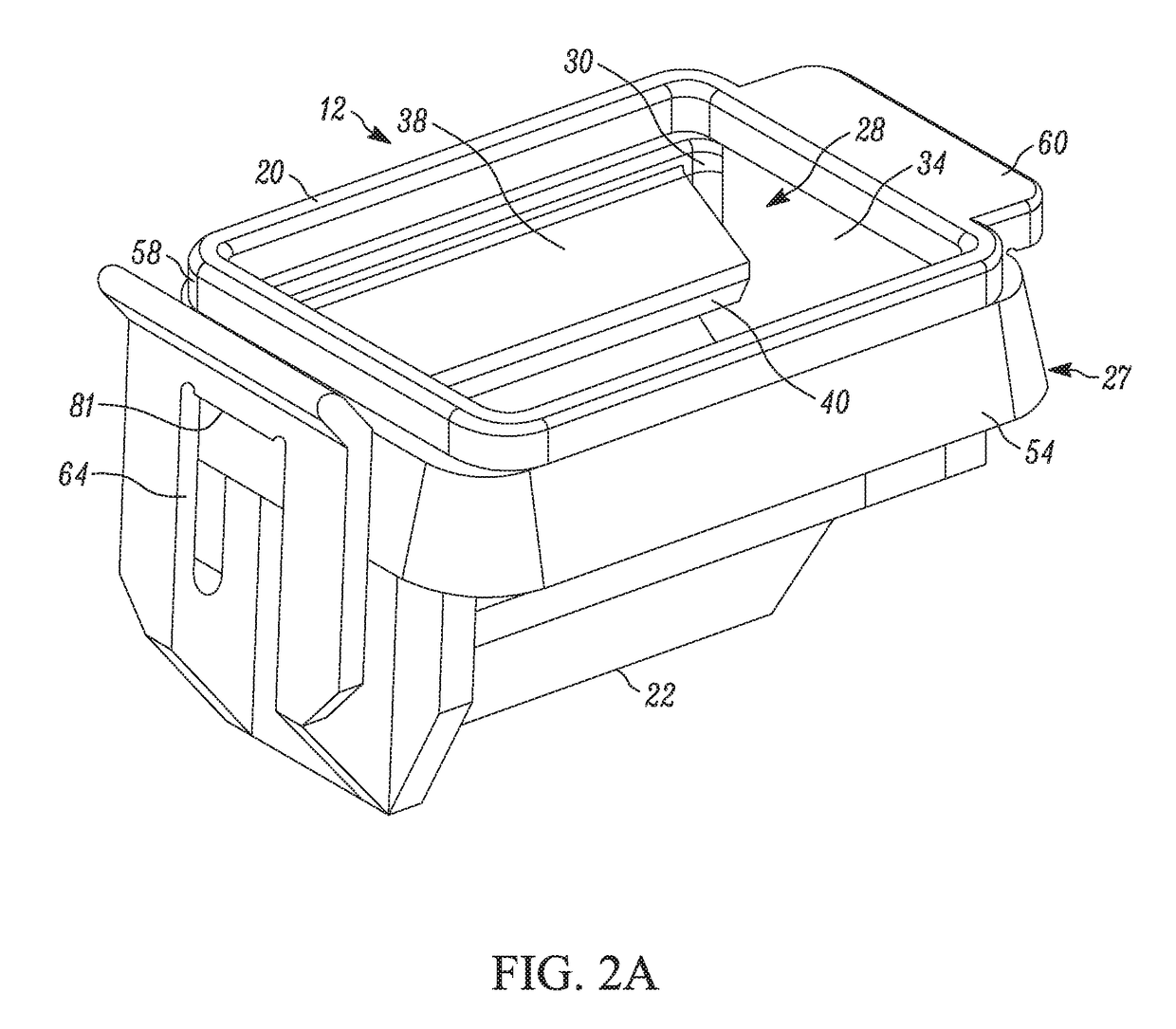
[0035]FIG. 1 shows an exemplary embodiment of a ball channel assembly 10 that includes a ball channel 12 installed in a mounting panel 14. A representative portion of a ball stud 16 is illustrated that includes a spherical head 18 engaged with the ball channel 12. The mounting panel 14 can be secured to or formed integrally with another component, such as a headlamp assembly. FIGS. 2A-2C provide various exemplary views of the ball channel 12. The ball channel 12 includes a channel top 20, a channel bottom 22, a front end wall 24, and a rear end wall 26 forming an outer portion 27. A first inner sidewall 30 situated opposite a second inner sidewall 32, and a first end wall 34 situated opposite a second end wall 36 form at least in part, an inner portion 28. In at least some embodiments, the first inner sidewall 30, second inner sidewall 32, first end wall 34, and second end wall 36, are distinct wall portions, while in other embodiments, they can be partially or wholly integrated wit...


PUM


Abstract

A ball channel and ball channel assembly are disclosed with the ball channel having a channel top, a channel bottom, and an inner portion including a first inner sidewall, a second inner sidewall, a first end wall, and a second end wall. A first resilient tab extends from the first inner sidewall with a first tab end surface, and a second resilient tab extends from the second inner sidewall with a second tab end surface. An elongated gutter extends longitudinally along the inner portion and adjacent the channel bottom, wherein the combination of the first and second tab end surfaces and a gutter top surface form a ball track for receiving a head of a ball stud and allowing secured sliding longitudinal movement of the head. An outer portion is also provided having a flange wall that is configured to engage a receiving wall of a mounting panel.

Description

CROSS-REFERENCE TO RELATED APPLICATION[0001]This application claims priority to U.S. Provisional Patent Appl. No. 62 / 296,028 filed on Feb. 16, 2016, the disclosure of which is incorporated herein by reference in its entirety for all purposes.FIELD OF THE INVENTION[0002]The present invention relates generally to the field of pivot joint fasteners and has been found particularly useful as a pivot joint for connecting a headlamp adjuster to a reflector of a headlamp assembly. In particular, the present invention is a ball channel assembly that permits a ball stud to both pivot within and slide along the length of a track.BACKGROUND OF THE INVENTION[0003]Pivotable spherical joints, commonly referred to as ball joints, generally include a ball stud engaged in a socket. Such joints have a wide variety of applications where a pivotable connection between two parts is desirable. For example, they may be used in many types of linear actuators and have been found to be particularly useful in ...

Claims


Application Information

Patent Timeline
IPC IPC(8): F16C11/06B60Q1/06
CPCF16C11/0623B60Q1/06B60Q2200/32F16C11/06B60Q1/076F16C11/0642F16C11/069F16C11/103F16C29/007F16C2326/01F16M11/14Y10T403/32073
Inventor BURTON, JOHN E.
Owner BURTON TECH
Why Eureka
Eureka Blog
Learn More