Eureka AIR delivers breakthrough ideas for toughest innovation challenges, trusted by R&D personnel around the world.

Ball stud track assembly

Active Publication Date: 2019-12-26
BURTON TECH
View PDF0 Cites 1 Cited by
  • Summary
  • Abstract
  • Description
  • Claims
  • Application Information

AI Technical Summary

Benefits of technology

The present invention is a ball stud track assembly that can be connected to a boss in a headlamp reflector assembly. It allows the ball to move freely within the track, with minimal force required to insert it, and offers resistance to remove it easily.

Problems solved by technology

This configuration results in a condition where the ball stud may be pulled out of socket under certain conditions of operation, such as vibration while supporting heavier reflectors, or in heavier headlamp assemblies, like the one previously referenced in U.S. Pat. No. 5,360,282, leaving the adjuster non-operational.
Though pull-out of the ball stud is resisted to some degree of success, but if enough pull-out force is applied, the tabs deflect, and the ball stud head slips through and “pops out.” Reducing the flexibility of tabs is not a desirable option because it would either be too difficult to insert the ball stud head into the socket, or the elasticity of the tabs would be lessened to the degree that they would break off during insertion of the ball stud.
Most existing ball-sockets are not able to achieve such a low insertion force without sacrificing pull-out resistance due to their construction.
Unfortunately, it is often desired to achieve a pull-out force resistance of 400N or higher.

Method used


Image

  • Ball stud track assembly
  • Ball stud track assembly
  • Ball stud track assembly

Examples


Embodiment Construction

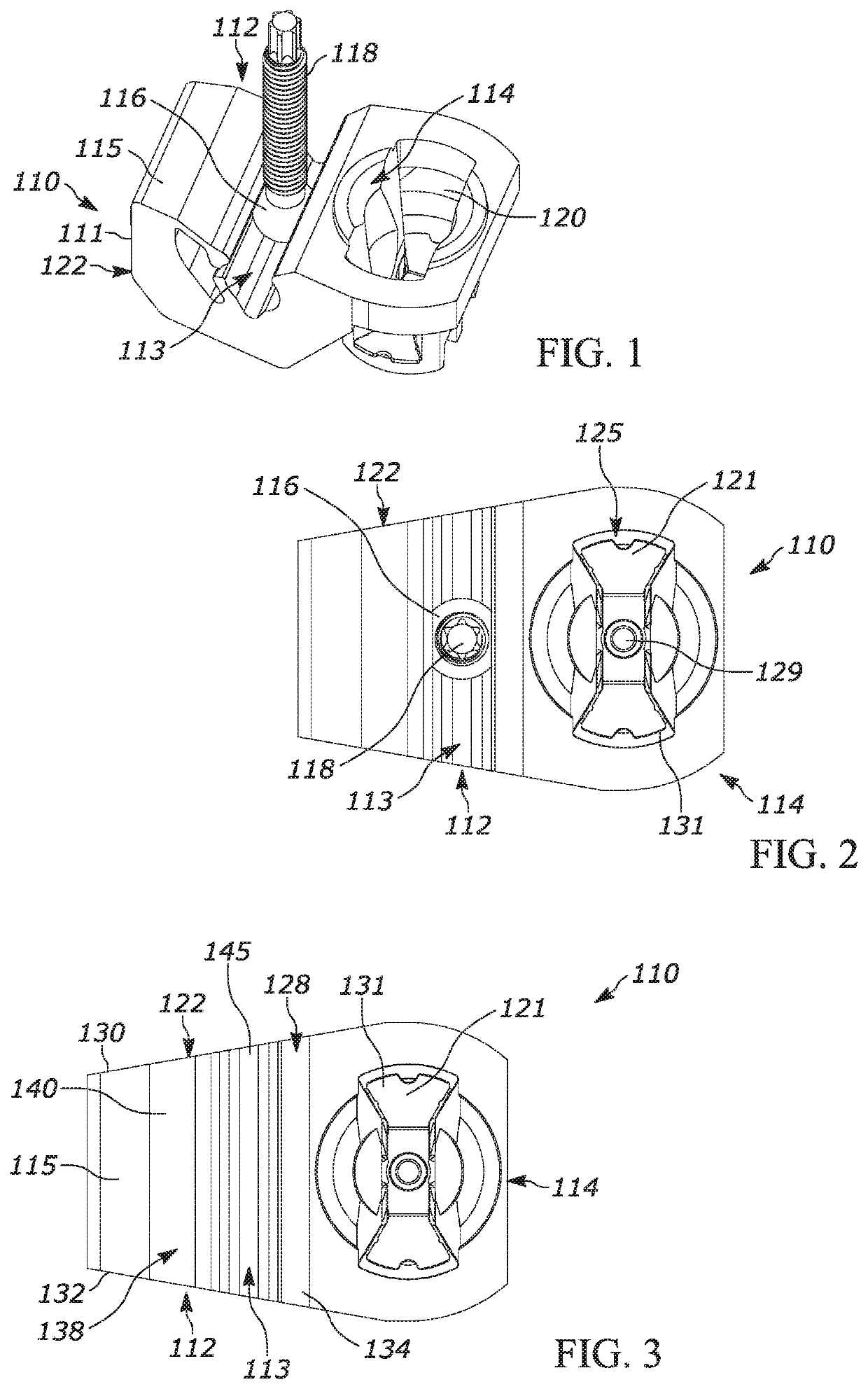
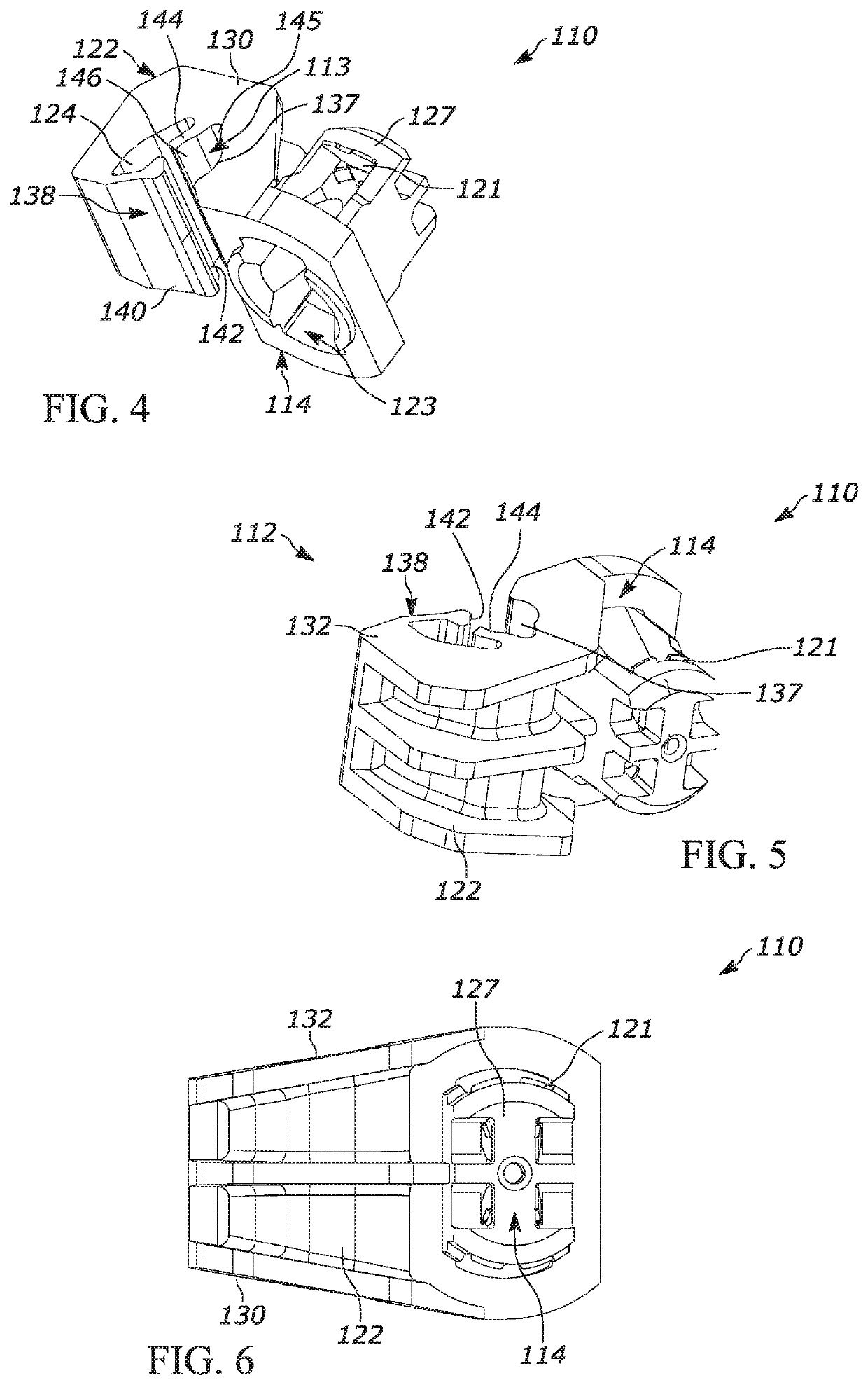
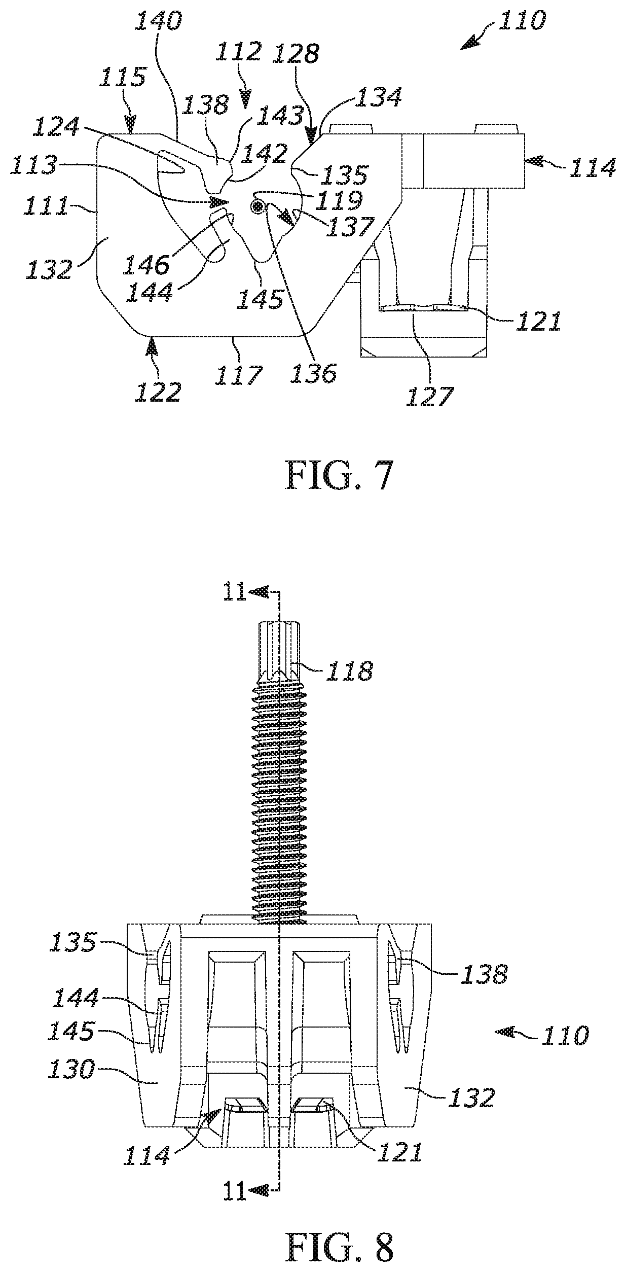
[0055]Referring to FIGS. 1 and 2, an exemplary embodiment of a ball stud track assembly 110 is shown that includes a base 122, having a ball track 112 and a connector portion 114. The ball track 112 includes a top 115, a bottom 117, and a ball channel 113 that is sized and shaped for receiving and securing a ball stud head 116 of a ball stud 118, while allowing sliding longitudinal movement of the ball stud head 116 along a central longitudinal ball channel axis 119 (FIG. 7), while restricting extraction of the ball stud head 116 from the ball channel 113. In FIG. 1, the ball stud track assembly 110 is shown with the ball stud head 116 of the ball stud 118 is secured within the ball channel 113, and the connector portion 114 secured to a complimentary mounting boss 120. The ball stud 118 is representative of a typical ball stud found in an adjuster mechanism (not shown) and the mounting boss 120 is representative of a receiving / engagement portion of a structure for securement of the...


PUM


Abstract

A ball stud track assembly is provided that includes a ball track and connector portion, the ball track comprising a back inner sidewall having a lower portion with a lower portion top surface and an upper portion having a retention ridge, an upper retaining arm extending from a front inner sidewall of the ball track and terminating at an upper arm end portion surface, and a lower retaining arm extending from the lower portion of the back inner sidewall and having a lower arm top surface, the upper arm end portion surface, the lower portion top surface, and the lower arm top surface extend to form a longitudinal ball channel having a central longitudinal ball channel axis, the ball channel configured to receive a ball stud head and allow sliding longitudinal movement, while restricting movement of the ball stud head along axes perpendicular to the central longitudinal ball channel axis.

Description

CROSS-REFERENCE[0001]This application is based on U.S. Provisional Patent Application Ser. No. 62 / 687,321 filed on Jun. 20, 2018, of which priority is claimed and the disclosure of which is incorporated herein by reference for all purposes.FIELD OF THE INVENTION[0002]The present invention relates generally to the field of pivot joint fasteners and has been found particularly useful as a pivot joint for connecting a headlamp adjuster to a reflector of a headlamp assembly. In particular, the present invention is a ball stud track assembly that permits a ball stud to both pivot within and slide along the length of a track.BACKGROUND OF THE INVENTION[0003]Pivotable spherical joints, commonly referred to as ball joints, generally include a ball stud engaged in a socket. Such joints have a wide variety of applications where a pivotable connection between two parts is desirable. For example, they may be used in many types of linear actuators and have been found to be particularly useful in...

Claims


Application Information

Patent Timeline
IPC IPC(8): F16C11/06
CPCF16C11/0695B60Q2200/32F16C11/0623B60Q1/068F16B35/06F16C11/0614F16C11/0685F21S41/39F21V17/12F16C2326/01F16C11/0657
Inventor BURTON, JOHN E.
Owner BURTON TECH
Why Eureka
Eureka Blog
Learn More