
LED panel

Inactive Publication Date: 2018-11-01
HARTING ELECTRIC GMBH & CO KG
View PDF11 Cites 1 Cited by
  • Summary
  • Abstract
  • Description
  • Claims
  • Application Information

AI Technical Summary

Benefits of technology

The present invention provides an LED panel that is easy to design and is not affected by the environment.

Problems solved by technology

The connecting means of DE 20 2010 008 460 U1 are separate parts, which makes the installation of display panels composed of such panels difficult.
Wiring of this kind is susceptible to moisture, which increases the susceptibility of a display panel consisting thereof to fail.

Method used


Image

  • LED panel
  • LED panel
  • LED panel

Examples


Embodiment Construction

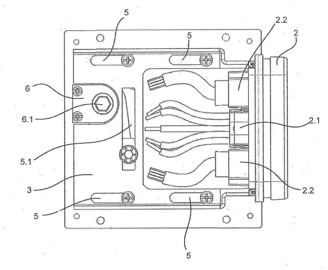
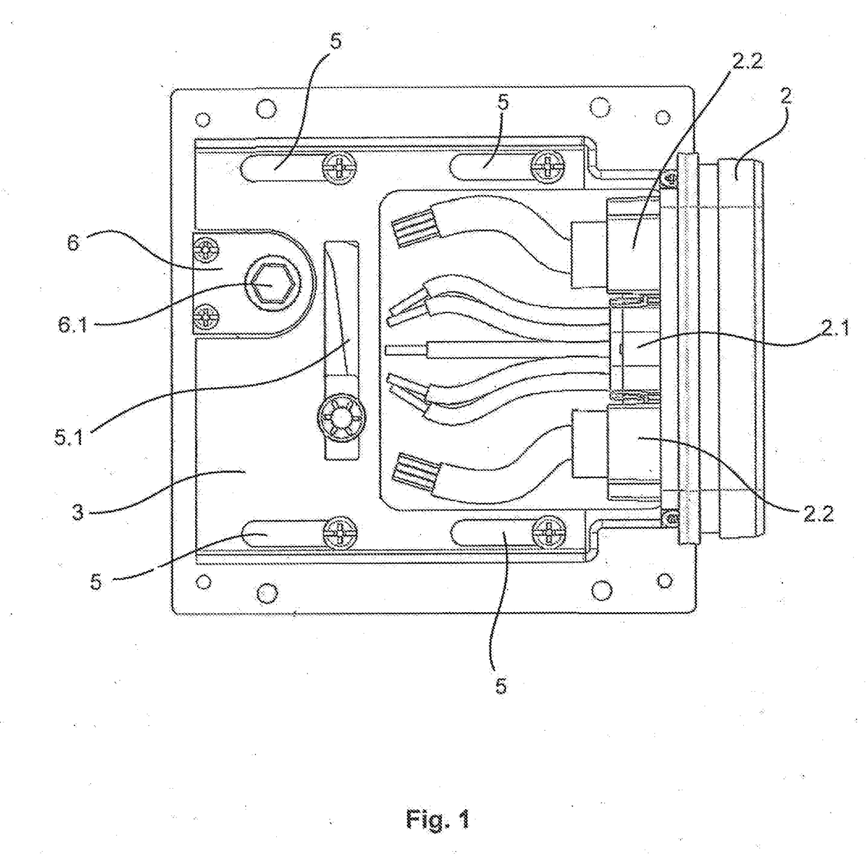
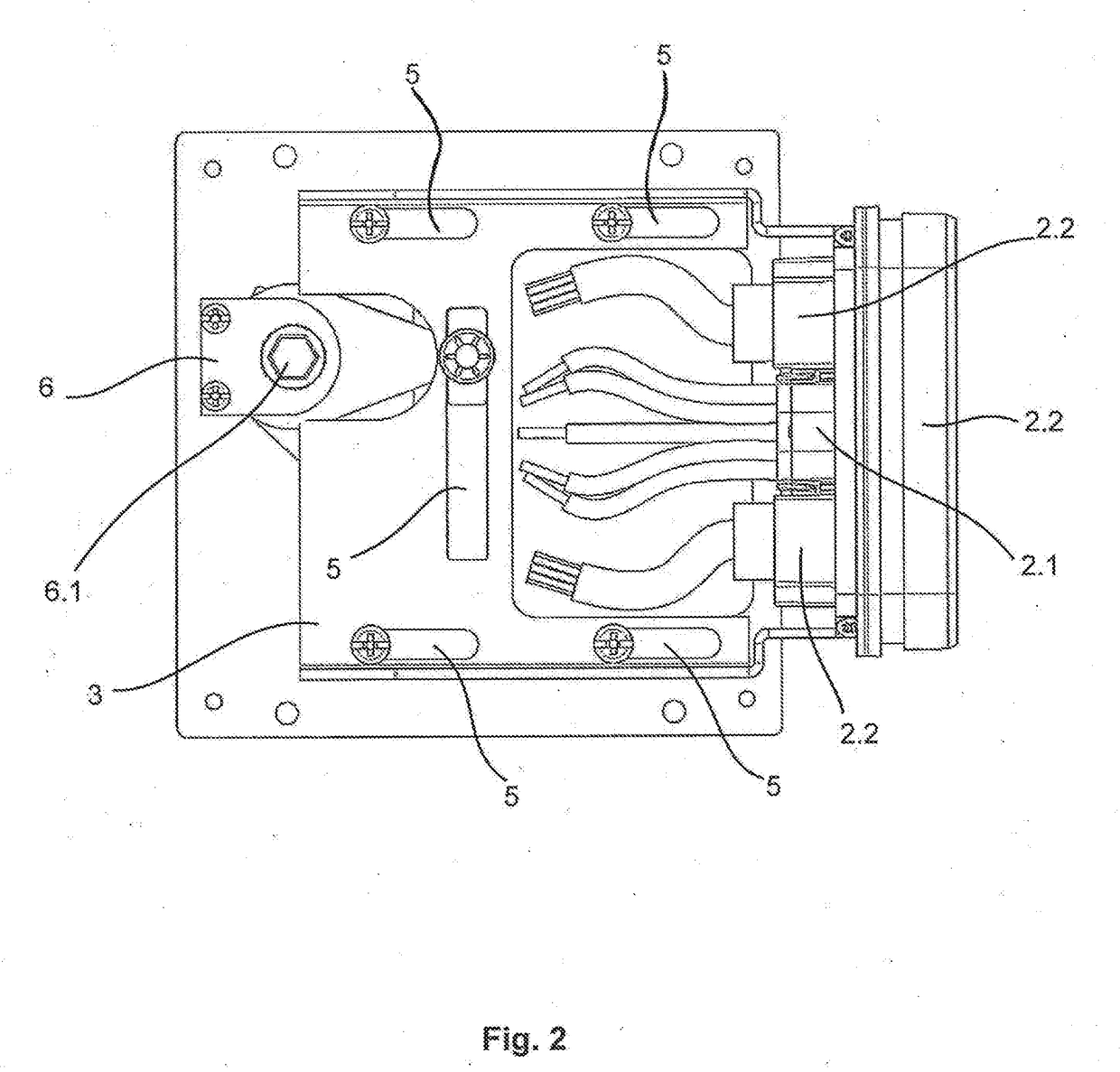
[0052]FIG. 1 shows a plan view of a contact-connection device or means 2 and a unit 3 of a panel 1. In this case, the contact-connection device or means 2 and the unit 3 are arranged opposite one another. The unit 3 and hence also the contact-connection device or means 2 are in this case illustrated in a disconnected state T.

[0053]The contact-connection device or means 2 comprises or consists of a plug-type connector, in particular of a hybrid plug-type connector. In this embodiment, the plug-type connector has two plug-type connectors for signal / data transmission 2.2, wherein in this case RJ45 plug-type connectors are used. The contact-connection device or means 2 furthermore has a plug-type connector for power transmission 2.1 using five power contacts. In this case, the plug-type connector for power transmission 2.1 is arranged between the two plug-type connectors for signal / data transmission 2.2. Corresponding conductors are arranged at the respective plug-type connectors, said ...


PUM


Abstract

The disclosure relates to an LED panel, which has at least one illuminant. The panel also has a contact-connection device or means, which can be used to electrically connect the panel to at least one further panel or an entire panel wall, such as a display board or an advertising wall, for example. The individual panel further has a unit, which can be used to displace the contact-connection device or means such that said panel can be repaired and replaced without difficulty.

Description

BACKGROUNDTechnical Field[0001]The disclosure relates to an LED panel which has at least one illuminant.[0002]LED panels of this kind can be combined to form display panels. Display panels are used in sports stadiums or are mounted on buildings for advertising purposes, for example.Description of the Related Art[0003]DE 20 2010 008 460 U1 shows a panel that can be mechanically connected to a further panel by way of a connecting means to form a display panel. Each individual panel contains a passage opening serving for individual power supply.[0004]The connecting means of DE 20 2010 008 460 U1 are separate parts, which makes the installation of display panels composed of such panels difficult.[0005]The panels of DE 20 2010 008 460 U1 are electrically wired on the rear side. Wiring of this kind is susceptible to moisture, which increases the susceptibility of a display panel consisting thereof to fail.[0006]Furthermore, plug-type connector systems that can be used to connect different...

Claims


Application Information

Patent Timeline
IPC IPC(8): G09F19/22H01R12/71H01R13/518G09F9/302G09F9/33
CPCG09F19/226H01R12/716H01R13/518G09F9/3026G09F9/33F21Y2115/10F21S8/00F21V15/04F21V21/002
Inventor SCHMIDT, HARTMUTH
Owner HARTING ELECTRIC GMBH & CO KG
Features
  • Generate Ideas
  • Intellectual Property
  • Life Sciences
  • Materials
  • Tech Scout
  • Unparalleled Data Quality
  • Higher Quality Content
  • 60% Fewer Hallucinations
Learn More