Lockable tilting assembly for motor vehicle

a technology of locking mechanism and motor vehicle, which is applied in the direction of cycle, transportation and packaging, gearing, etc., can solve the problems of only locking in a full extension position, and inability to stabilize the vehicl

Inactive Publication Date: 2018-11-08
GOEL HERSH
View PDF8 Cites 7 Cited by
  • Summary
  • Abstract
  • Description
  • Claims
  • Application Information

AI Technical Summary

Benefits of technology

[0007]The present invention discloses a three-wheeled motor vehicle having a lockable tilting mechanism. The tilting mechanism is configured to all the vehicle to freely tilt at any angle according to the driving conditions. The tilting mechanism is further configured to lock the tilting of the vehicle at any desired angle by the driver. The tilting mechanism is further configured to correct the lean or tilt angle from inside the vehicle without the need for driver to put their feet on the ground outside the vehicle. The tilting mechanism is further configured to enable the driver to lock or unlock the lean of the vehicle in a manner that allows the driver to intuitively switch between steering and counter-steering.

Problems solved by technology

At low speeds these vehicles are in an unstable equilibrium and the driver needs to usually place their feet on the road to keep such vehicle upright and prevent toppling.
However, these mechanical arms only lock in a position of full extension and cannot stabilize a vehicle that is already in a lean.
Any attempt to deploy the mechanical arm while the vehicle is already leaning into a turn will likely result in an adverse outcome.
This prevented widespread adoption of this vehicle.
This is because the driver fails to ‘counter steer’ the vehicle after the vehicle automatically unlocks the tilt functionality.
This identifies another problem with current state of art of vehicles having a lockable tilt mechanism—the inability of the driver to intuitively switch between steering and countersteering.

Method used


Image

  • Lockable tilting assembly for motor vehicle
  • Lockable tilting assembly for motor vehicle
  • Lockable tilting assembly for motor vehicle

Examples


Embodiment Construction

[0022]A description of embodiments of the present invention will now be given with reference to the Figures. It is expected that the present invention may be embodied in other specific forms without departing from its spirit or essential characteristics. The described embodiments are to be considered in all respects only as illustrative and not restrictive. The scope of the invention is, therefore, indicated by the appended claims rather than by the foregoing description. All changes that come within the meaning and range of equivalency of the claims are to be embraced within their scope.

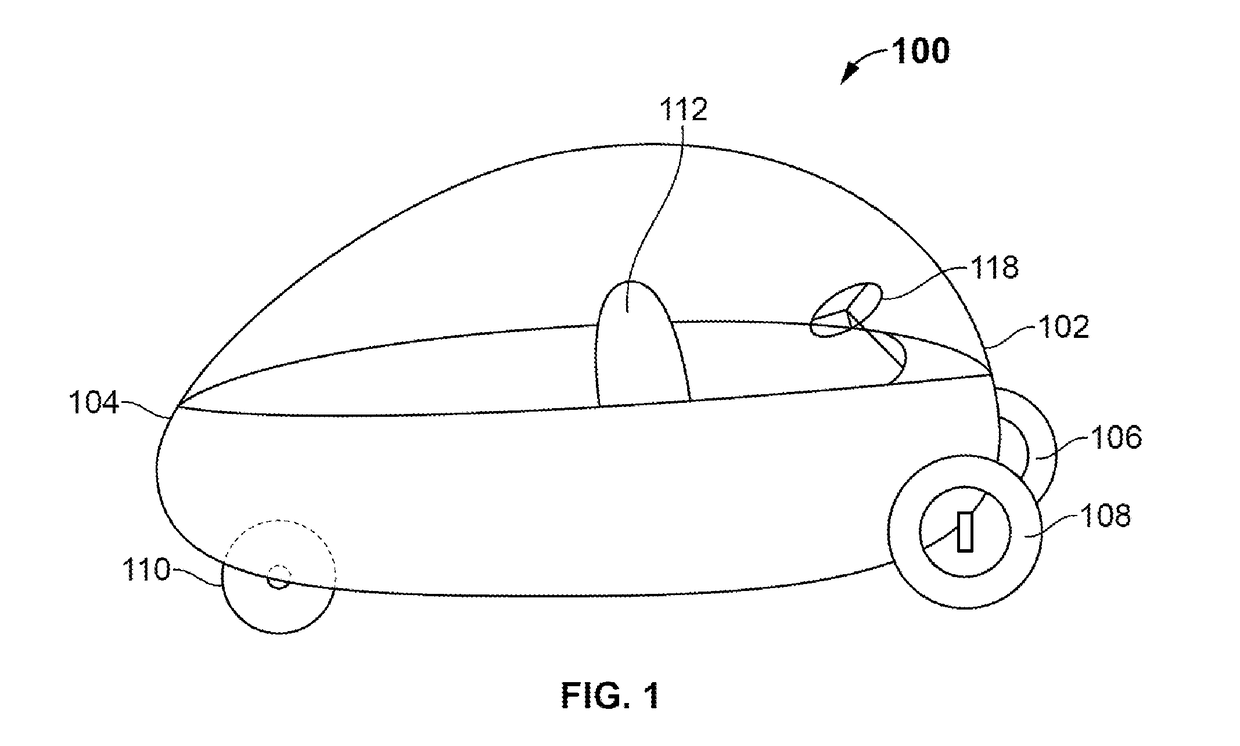
[0023]Referring to FIG. 1 illustrates a three-wheeled tilting vehicle 100 having a lockable tilting mechanism. The three-wheeled tilting vehicle 100 comprises a front section 102 and a rear section 104. The front section 102 of the vehicle 100 comprises a lockable tilting mechanism. The tilting mechanism or assembly of the vehicle 100 comprises two front wheels 106 and 108. The rear section 104 of t...


PUM


Abstract

The present invention discloses a three-wheeled motor vehicle having a lockable tilting mechanism. The tilting mechanism is configured to tilt the vehicle at any angle without the need for a driver to put their feet on the ground outside the vehicle. The tilting mechanism is further configured to lock the tilting of the vehicle at any desired angle by the driver. The present invention enables the driver to alter the lean from within the vehicle if the lean is locked in an undesirable position. The tilting mechanism is further configured to enable the driver to lock or unlock the lean of the vehicle in a manner that allows the driver to intuitively switch between steering and counter-steering.

Description

BACKGROUND OF THE INVENTIONA. Technical Field[0001]The present invention generally relates to motor vehicles, and more specifically relates to a three-wheeled vehicle having a lockable tilting mechanism.B. Description of Related Art[0002]In general, several vehicles (such as motorcycles) are designed to lean from one side to another for turning the vehicles at high speeds. These vehicles may also have more than two wheels. For vehicles with three or more wheels that lean (for example the Piaggio MP3 scooter), a conformational change is effected to allow leaning while the vehicle is still keeping all its wheels on the ground. The act of leaning or tilting effectively moves the centre of mass of a vehicle laterally i.e., perpendicular to the direction of travel as well as the vertical axis. In a ‘freely leaning’ vehicle, this lateral displacement of the centre of mass is accomplished by letting the vehicle fall a little bit to the side under the influence of gravity. Thus, such tiltin...

Claims


Application Information

Patent Timeline
Patent Type & Authority Applications(United States)
IPC IPC(8): B60G21/00B62D61/06B62D9/02B62D9/04F16H1/16
CPCB60G21/007B62D61/065B62D9/02B62D9/04F16H1/16F16H2019/046B62K5/10B60G2300/122B60G2300/45B62K5/05B62K5/08
Inventor GOEL, HERSH
Owner GOEL HERSH
Why Eureka
Try Eureka