Rigid connection structure between upper precast concrete column and lower precast concrete column and rigid connection structure of precast concrete beam using the same

Inactive Publication Date: 2018-11-08
UNIV IND COOP GRP OF KYUNG HEE UNIV
View PDF3 Cites 5 Cited by
  • Summary
  • Abstract
  • Description
  • Claims
  • Application Information

AI Technical Summary

Benefits of technology

[0010]Accordingly, the present invention has been made in view of the above-mentioned problems occurring in the prior art, and it is an object of the present invention to provide to a rigid connection structure between an upper PC column and a lower PC column and a rigid connection structure of a PC beam using the same that impro

Problems solved by technology

The method for simply mounting the PC beam onto the PC column is one of methods widely used currently, which is capable of somewhat reducing the construction period, but since a column and beam connection in the method is made through simple jointing, a moment cannot be transferred in this method when a lateral force like an earthquake is applied.
Accordingly, lateral force reinforcing means like shear walls, braces and so on should be additionally located, thereby failing to provide the advantages of the PC method planned for reducing the construction period and unavoidably increasing construction cost and period.
When the PC beam is simply mounted on the PC column, further, the escape of the column-beam connection may be generated to cause safety accidents.
Accordingly, the structural instability in the column-beam connect

Method used


Image

  • Rigid connection structure between upper precast concrete column and lower precast concrete column and rigid connection structure of precast concrete beam using the same
  • Rigid connection structure between upper precast concrete column and lower precast concrete column and rigid connection structure of precast concrete beam using the same
  • Rigid connection structure between upper precast concrete column and lower precast concrete column and rigid connection structure of precast concrete beam using the same

Examples


first embodiment

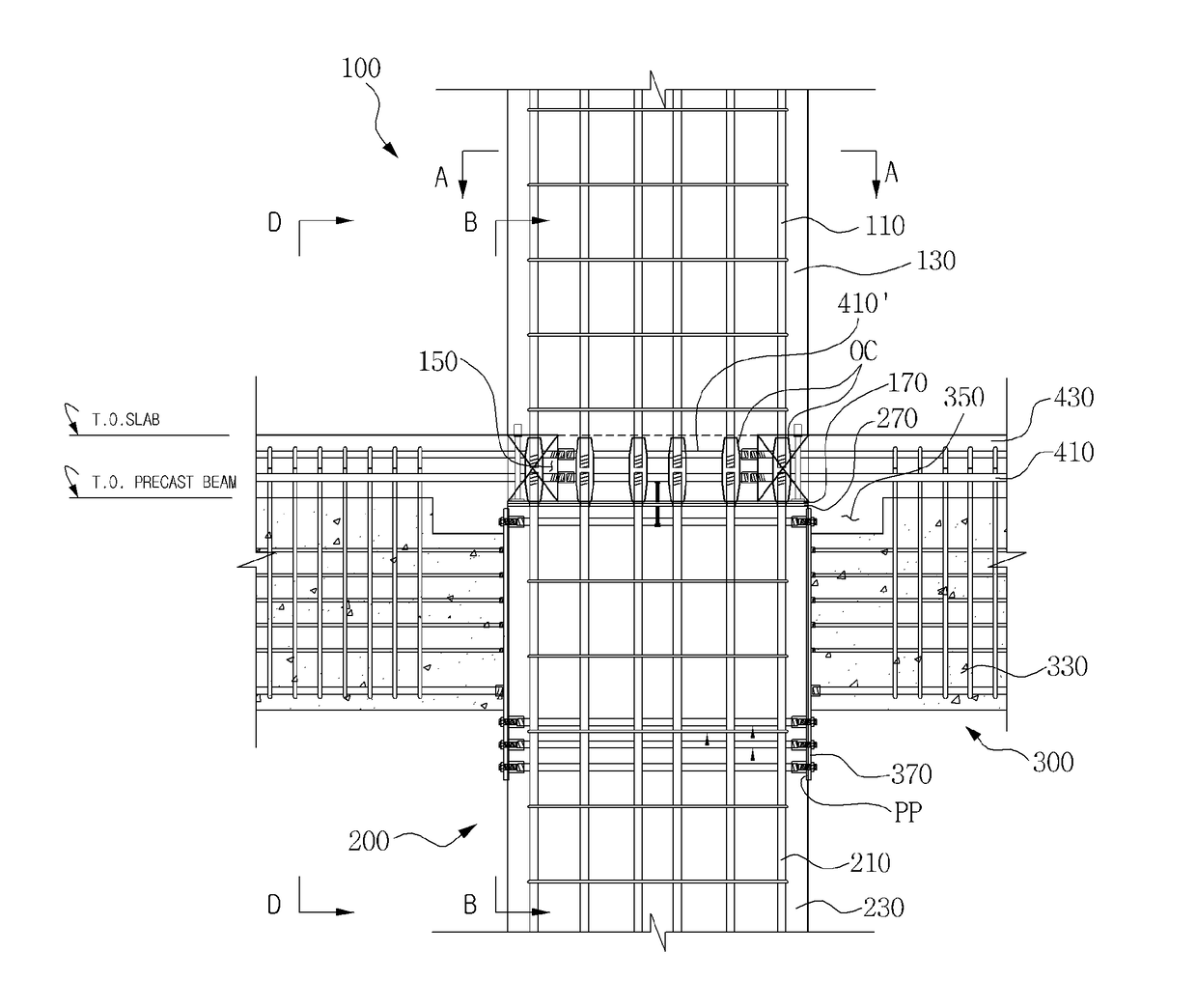
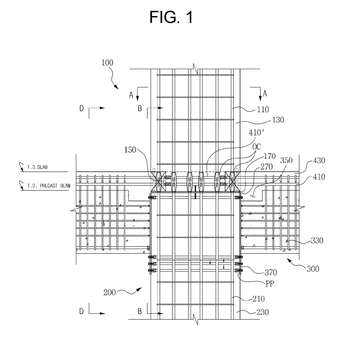
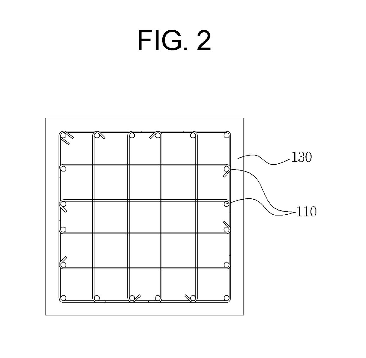
[0035]FIG. 1 is a front sectional view showing a rigid connection structure between an upper PC column and a lower PC column and a rigid connection structure of a PC beam using the same according to the present invention, FIG. 2 is a sectional view taken along the line A-A of FIG. 1, and FIG. 3 is a sectional view taken along the line B-B of FIG. 1.

[0036]FIG. 4 is an enlarged view of FIG. 1, FIG. 5 is a sectional view taken along the line D-D of FIG. 1, and (a) and (b) of FIG. 6 are top views showing an upper column plate and a lower column plate of FIG. 1.

[0037]FIG. 7 is a perspective view of FIG. 1.

[0038]A rigid connection structure between an upper PC column 100 and a lower PC column 200 according to a first embodiment of the present invention includes: the lower PC column 200 having column concrete 230, a lower column plate 270 disposed on top of the column concrete 230, and a plurality of lower column reinforcing bars 210 buriedly arranged vertically in the interior of the colu...

fourth embodiment

[0049]FIG. 16 is a sectional view showing a rigid connection structure between an upper PC column and a lower PC column and a rigid connection structure of a PC beam using the same according to the present invention, FIG. 17 is a perspective view showing the PC beam of FIG. 16, and FIG. 18 is an enlarged view of FIG. 16.

[0050]Referring analogically to the PC beam of FIG. 16, a rigid connection structure of a PC beam 300′ using the rigid connection structure between the upper PC column 100 and the lower PC column 200 according to the present invention includes: the PC beam 300′ having beam concrete 330, a beam plate 370 disposed on the side of the beam concrete 330, a plurality of beam reinforcing bars 310 buriedly arranged vertically in the interior of the beam concrete 330 to maintain the cover thickness of concrete and each having one end connected to the beam plate 370, and a beam bracket 340 having one end connected to the beam plate 370; beam upper reinforcing bars 410 arranged...

second embodiment

[0054]FIG. 11 is an enlarged front sectional view showing a rigid connection structure between an upper PC column and a lower PC column and a rigid connection structure of a PC beam using the same according to the present invention, and (a) and (b) of FIG. 12 are top views showing an upper column plate and a lower column plate of FIG. 11.

[0055]As shown in FIG. 11, a rigid connection structure between an upper PC column 100 and a lower PC column 200 according to the second embodiment of the present invention includes: the lower PC column 200 having column concrete 230, a lower column plate 270 disposed on top of the column concrete 230, and a plurality of lower column reinforcing bars 210 buriedly arranged vertically in the interior of the column concrete 230 to maintain the cover thickness of concrete and having upper ends penetrated into the lower column plate 270 in such a manner as to be exposed to the outside; and the upper PC column 100 having column concrete 130, an upper colu...


PUM


Abstract

Provided is a rigid connection structure including: a lower PC column having column concrete, a lower column plate disposed on top of the column concrete, and a plurality of lower column reinforcing bars buriedly arranged vertically in the interior of the column concrete and having upper ends penetrated into the lower column plate in such a manner as to be exposed to the outside; and an upper PC column having column concrete, an upper column plate disposed on top of the column concrete, and a plurality of upper column reinforcing bars buriedly arranged vertically in the interior of the column concrete and having lower ends penetrated into the upper column plate in such a manner as to be exposed to the outside.

Description

BACKGROUND OF THE INVENTIONField of the Invention[0001]The present invention relates to a rigid connection structure between an upper precast concrete column and a lower precast concrete column and a rigid connection structure of a precast concrete beam using the same that improve a column-column connection and a column-beam connection, while performing moment connection, that is, rigid connection, in a dry construction method, thereby enhancing the constructability thereof to allow the rigid connection to be achieved only by the connection of reinforcing bars before concrete is cast on the connections.Background of the Related Art[0002]So as to ensure good constructability and reduce a construction period, recently, a precast concrete (hereinafter, referred to as “PC”) method has been increasingly adopted.[0003]Examples of the conventional PC method include a method for simply mounting a PC beam onto a PC column and a method for unitarily casting a PC column and a PC beam.[0004]The...

Claims


Application Information

Patent Timeline
IPC IPC(8): E04B1/21E04B1/41E04C3/34
CPCE04B1/215E04B2103/02E04C3/34E04B1/41E04C5/0645E04C5/163
Inventor HONG, WON KEEHWANG, DAE JIN
Owner UNIV IND COOP GRP OF KYUNG HEE UNIV
Why Eureka
Try Eureka