Retractable Syringe

a safety syringe and syringe technology, applied in the field of retractable safety syringes, can solve the problems of difficult or expensive manufacture, mechanism suffers from functional reliability issues, liquid leakage, etc., and achieves the effect of reducing or eliminating the leakage of fluid, and more economical construction

Active Publication Date: 2018-11-15
SAFER SYRINGE INNOVATIONS PTY LTD
View PDF2 Cites 0 Cited by
  • Summary
  • Abstract
  • Description
  • Claims
  • Application Information

AI Technical Summary

Benefits of technology

[0010]This type of syringe represents an improvement over the prior art in that leakage of fluid is reduced or eliminated, and also the syringe is of simpler, and therefore of more economical constructions. The instantaneous retraction of the needle inside the barrel via the biasing member (e.g. a spring) means the syringe can be used and disabled in one action, and with a one-handed operation.
[0011]Preferably, the detent arrangement comprises one or more indent regions in the needle hub, said indent region or regions having a profile that, when engaged would prevent movement of said hub, whether into or out of the barrel; and a set of resilient claws (e.g. three claws) that have a complementary profile to that of the indent or indents, that occupies the indent regions, thereby to lock the needle hub in place and defeating the force of the biasing member. More preferably, the internal profile of said indent is square or rectangular. The detent arrangement that holds the needle hub more firmly in place, by disallowing movement in both directions, provides a particular advantage.
[0012]In a preferred embodiment, the upper region of said claws have an inclined surface that is inclined away from the needle hub, such that when engaged by a member moving in the direction of injection, the force applied thereby will tend to push the claws away from the needle hub, thereby releasing it and allowing the biasing member to push the hub into the plunger. Such upper surfaces allow for a more reliable engagement of the claws, and allow simple engagement by another moving part to create a controlled disengagement of the claws.
[0013]Preferably, the plunger has at its liquid-engaging end a stopper, said stopper being held in place by a detent arrangement that may be overcome by the force of the biasing member pushing the needle hub into the plunger. This allows the plunger to be pushed back into the cavity along with the needle. It also makes the syringe easier to manufacture and allows a more efficiently shaped plunger stopper to be employed, such as one with a partly-spherical liquid-engaging surface.
[0014]In a preferred embodiment, the biasing member is a spring, and said spring is installed partly compressed. Partial compression of the spring (as opposed to full compression) allows for simpler construction and better control of the retraction operation.

Problems solved by technology

A drawback with this type of retractable syringe is that they are prone to liquid leakage, and the mechanism tends to suffer from functional reliability issues.
Other designs are relatively complex and so are difficult or expensive to manufacture.
Yet other designs do not allow for full dispensing of the injectable fluid, due to dead-zones being left in the barrel.

Method used


Image

  • Retractable Syringe
  • Retractable Syringe
  • Retractable Syringe

Examples


Embodiment Construction

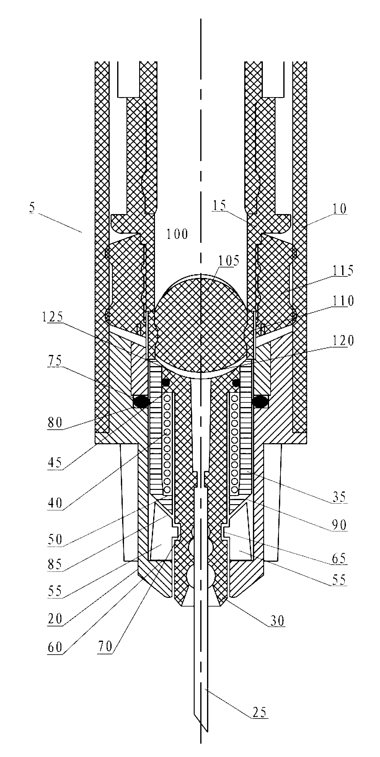
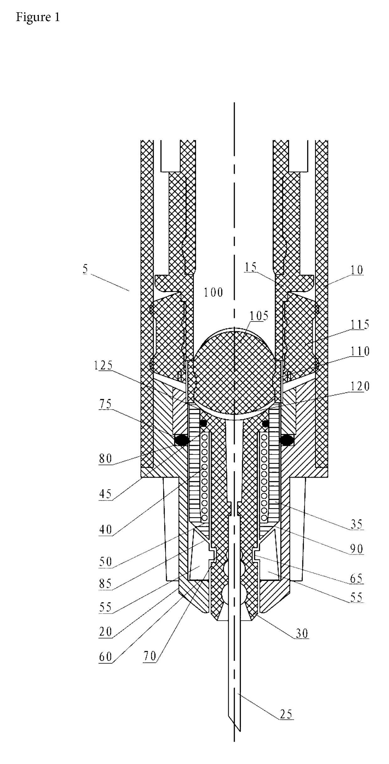
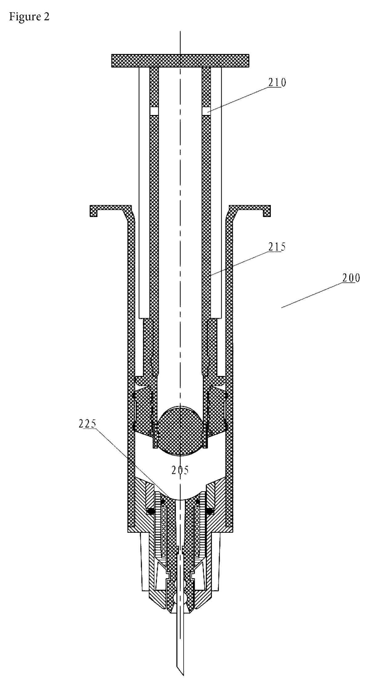
[0020]The invention may be embodied by the arrangement of working parts at the ‘dispensing’ end of a retractable hypodermic syringe. These are best understood by reference to the accompanying figures.

[0021]Turning to FIG. 1, there is shown an auto-retractable syringe 5. The major components of the syringe are the barrel 10, the plunger 15, the gland 20 and the needle 25. The gland 20 is inserted in the barrel 10 in a press-fit manner and houses the needle hub assembly. It is also possible for the gland to be a screw-in type.

[0022]The needle hub assembly includes the needle hub 30, in which is inserted the needle 25. A sliding activator sleeve 35 is fitted around the needle hub and in between these two parts is placed a partially compressed spring 40. The spring 40 is in contact with a stepped rear-facing surface 45 of the hub and an inner forward stepped surface 50 of the sleeve 35. Thus the spring's role is to tend to force the hub 30 rearward relative to the sleeve 35.

[0023]Howeve...


PUM


Abstract

An auto-retractable syringe having a barrel and a plunger wherein engagement of said plunger with an otherwise immobilised needle hub allows a biasing member to push the needle hub into a cavity in the plunger.

Description

TECHNICAL FIELD[0001]The invention relates to the field of hypodermic syringe manufacture. In particular, the invention relates to a retractable safety syringe, in which the needle is capable of being withdrawn into the barrel of the syringe after use via a spring or similar mechanism.BACKGROUND OF THE INVENTION[0002]Safety syringes for hypodermic needles are becoming a very important tool of healthcare. The ability to prevent needle-stick injuries is extremely important in preventing the spread of blood-borne diseases.[0003]One particular type of safety syringe is the retractable syringe. That is: a syringe wherein there is provided a mechanism, usually a spring, inside the syringe that is activated upon completion of the injection of the fluid, whereby the spring acts to retract the needle inside the syringe barrel. This prevents the needle from causing a needle-stick injury, and in particular it allows the needle operator to withdraw the needle via a one-handed operation, which m...

Claims


Application Information

Patent Timeline
Patent Type & Authority Applications(United States)
IPC IPC(8): A61M5/32
CPCA61M5/3234A61M2005/3236A61M5/508A61M5/3202A61M2005/3235A61M2005/3239
Inventor WALSH, ALLAN
Owner SAFER SYRINGE INNOVATIONS PTY LTD
Why Eureka
Try Eureka