Fluid-actuated workholder with a collet driven by a soft and thin bladder

a technology of fluid-actuated work holders and collets, which is applied in the field of work holders, can solve the problems of reducing fluid pressure, destroying the workholder, and not eliminating the high pressure conditions, so as to reduce or eliminate fluid leakage, and increase the expansion or contraction range.

Active Publication Date: 2015-02-03
HYDRA LOCK
View PDF16 Cites 7 Cited by
  • Summary
  • Abstract
  • Description
  • Claims
  • Application Information

AI Technical Summary

Benefits of technology

[0011]At least some of the objects, features and advantages that may be achieved by at least certain embodiments of the invention include providing a workholder that may have a bladder that is highly displaceable under relatively low fluid pressure to firmly hold a workpiece received adjacent to a driven member, may provide equal or greater holding power under lower fluid pressures compared to prior art devices, may have a greater expansion or contraction range, may reduce or eliminate fluid leakage, may be used to firmly hold and locate workpieces formed of cast material, may conform to a workpiece which is out of round, may dampen vibrations during the machining process, may provide a better finish of the part machined, may repeatably and reliably hold and locate workpieces, may reliably center each workpiece, may be formed of different thicknesses to accommodate different sized parts, may be displaced generally radially inwardly or radially outwardly, and may be of relatively simple design, economical manufacture and assembly, rugged, durable, reliable, and in service may have a long useful life.

Problems solved by technology

In extreme operating environments, such high pressures require concomitant energy consumption, may result in workholder leakage, and / or may cause the hard plastic bladder to extrude through slots in the collet, thereby permanently damaging the workholder.
Even though this approach is a relatively low cost solution, it does not eliminate the high pressure conditions.
Although this approach results in somewhat lower fluid pressures, it requires many additional parts of precision manufacture.
While this approach also results in lower fluid pressures, it too requires many additional parts of precision manufacture.

Method used


Image

  • Fluid-actuated workholder with a collet driven by a soft and thin bladder
  • Fluid-actuated workholder with a collet driven by a soft and thin bladder
  • Fluid-actuated workholder with a collet driven by a soft and thin bladder

Examples


Embodiment Construction

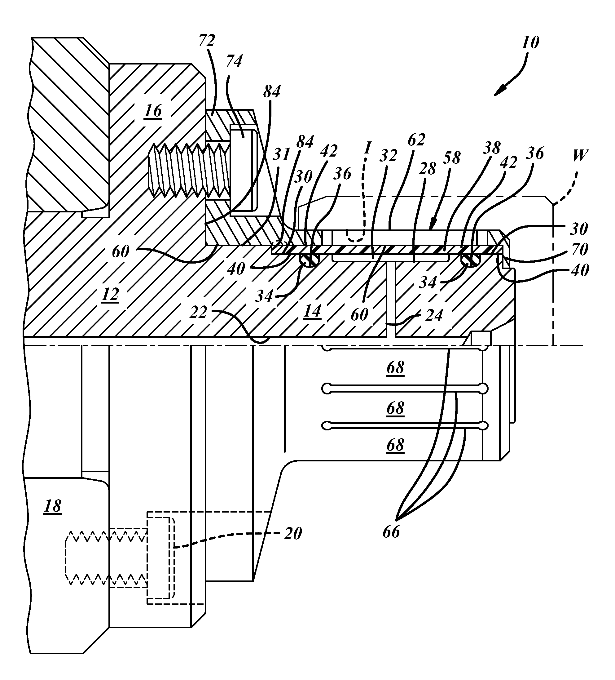
[0016]Referring in detail to the drawings, FIG. 1 illustrates a hydrostatic workpiece holder, and more specifically, a hydrostatic arbor 10. The arbor 10 includes a main body 12 that may have a cylindrical shaft or mandrel portion 14 and a radially extending mounting flange portion 16. The body 12 may be constructed to be mounted on a machine tool spindle 18 by suitable cap screws 20 as shown. The body 12 may include a main fluid passage 22 and one or more branch fluid passages 24 that are constructed to be filled with a pressurized fluid. The main fluid passage 22 may be supplied with pressurized fluid from a pump carried by the body 12 or through the machine tool spindle 18 by a remote pump. Because such low pressures are required to activate the arbor 10, pressurized air, instead of oil, may be used. The mandrel portion 14 of the body 12 may include an external annular recess 28 in a first outer diameter or first outer surface 30 of the mandrel portion 14 to at least partially de...


PUM


Abstract

A workholder to hold a workpiece, including a main body partially defining a fluid chamber, and a bladder carried by the main body with an interference fit, further defining the fluid chamber, and composed of an 80 to 100 durometer Shore A scale hardness polymer of a 12:1 to 18:1 diameter-to-wall-thickness ratio. Annular seals may further define the fluid chamber, and are disposed radially between the bladder and main body and axially adjacent the fluid chamber, and are composed of a 60 to 80 durometer Shore A scale hardness polymer. A collet is carried and driven by the bladder for gripping engagement with the workpiece.

Description

FIELD OF THE INVENTION[0001]The present invention relates to work holders and, more specifically, to a fluid-actuated work holder having a bladder-driven collet.BACKGROUND OF THE INVENTION[0002]Workpiece holders, or workholders, have been used for decades and are useful for holding solid and annular workpieces for subsequent machining or grinding. A first type of hydraulic workholder includes a main body, a circumferentially continuous steel sleeve carried on the body to grip a workpiece, and a hydraulic fluid chamber defined between the body and sleeve and sealed by rubber O-rings therebetween. A second type of hydraulic workholder includes a main body, a slotted steel sleeve or collet carried by the main body, a relatively hard (85 durometer Shore D scale) plastic bladder carried between the main body and the collet, and a hydraulic fluid chamber defined between the body and bladder and sealed by soft (70 durometer Shore A scale hardness) rubber O-rings therebetween.[0003]With bot...

Claims


Application Information

Patent Timeline
Patent Type & Authority Patents(United States)
IPC IPC(8): B23B31/30B23B31/20B23B31/40
CPCB23B31/402B23B31/204B23B31/305B23B2226/63B23B2260/042Y10T279/1029Y10T279/1216
Inventor ANDRE, WILLIAM M.
Owner HYDRA LOCK
Why Eureka
Try Eureka